Image Processing Reference
In-Depth Information
3 Implementation
The main effort of this research is the use of image processing of captured images of a digital
camera. The images used in this project and the video were taken by an inexpensive Canon
with very high accuracy, full HD with 30 frames/s. Throughout this section, the design essen-
tials, basics, and procedure will be discussed separately.
FIGURE 1
Canon 500 D digital camera.
The desired system should be able to meet the requirements and goals stated below:
• Ability to detect the speed of the vehicle that crosses the traffic light with accuracy of 15%.
• Ability to recognize the vehicle registration plate with accuracy of 75%.
• Ability to identify cars crossing the red light.
4 Traffic detectors
This section describes current technology associated with traffic control.
4.1 Induction Loops
Inductive-loop detector technology has been in use for the detection of vehicles since the early
is It consists of a loop of wire and an electronic detection unit. Simply, the operation is
based on the principle of metal detection, relying on the fact that a moving metal will induce
an electrical current in a nearby conducting wire. With a vehicle detector, the loop is buried in
the roadway and the object to be detected is a vehicle (as shown in
Figure 2
).
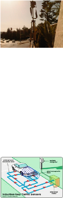
FIGURE 2
Induction loop.
Vehicle-detection loops are used to detect vehicles passing a certain area; for our approach,
a traffic light. An insulated, electrically conducting loop is installed in the pavement. The
electronic unit transmits energy into the wire loops at frequencies between 10 and 200 kHz,
depending on the model. The inductive-loop system behaves as a tuned electrical circuit in
which the loop wire is considered as the inductive elements. When a vehicle passes over the
loop or is stopped over the loop, the vehicle induces eddy currents in the wire loops, which
Search WWH ::

Custom Search