Image Processing Reference
In-Depth Information
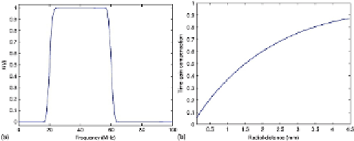
FIGURE 3
(a) Frequency response of the Butterworth FIR filter and (b) profile of TGC func-
tion.
2.3 Time Gain Compensation
The ultrasound is a mechanical wave and due to this nature, the intensity of the ultrasound
beam is atenuated as it penetrates the tissue.
To compensate for this loss in signal intensity, TGC is applied to each line in A-mode, which
is defined as
(1)
where
β
is the coeicient of atenuation and
r
is the radial distance from tip of catheter.
The range of the radial distance was extracted from the RF File Reader of exam ranging until
4.48 cm.
the problem of characterization of the atherosclerotic plaque. They define a value for the coef-
icient of atenuation as
β
= 0.4605 dB/cm, which was adopted in this work.
The profile of TGC function is shown in
Figure 3(b)
.
2.4 Signal Envelope
To show the changes stemming from the texture and not from the wave profile, the envelope
of the signal is obtained simply applying the Hilbert transform to each line in A-mode from
the RF signal,
Figure 4(a)
.

Search WWH ::

Custom Search