Global Positioning System Reference
In-Depth Information
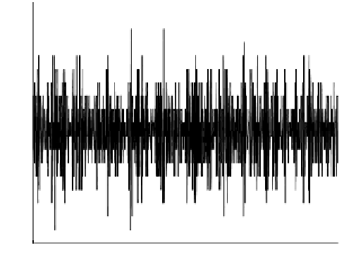
8
6
4
2
0
−2
−4
−6
−8
0
0.005
0.01
0.015
0.02
0.025
Time [ms]
FIGURE 4.4. Time domain. Representation of 1000 samples.
Referring to the design in Figure 4.2, a sampling frequency of 38.192 MHz
is used for the 47.74 MHz IF, and this provides a final digital frequency trans-
lation to an IF of 9.548 MHz. The resulting sampled information bandwidth of
[0-38.192/2] MHz provides more.
The final ADC parameter to be discussed is the analog input range. This range
defines the voltage range for which the quantization will be distributed across.
In the case of the ADS830 part, the minimum analog input range is 1 V peak-to-
peak. Assuming a 50
load, which is traditional in radio frequency design, a 1 V
−
signal corresponds to
17 dBW. Thus, it should now be clear why the amplifica-
tion within the RF chain is needed. It had been mentioned that it was to provide
suitable signal levels. The combination of thermal noise and received signal will
be simply too weak to exercise the bits in this or any ADC. So a goal of the am-
plifiers is to increase the received signal level, which again is dominated by the
thermal noise, to exercise the full range of the ADC.
Although not depicted in Figure 4.2, the final amplifier in many GNSS front-
end designs will be a variable gain with a feedback signal resulting from pro-
cessing implemented after the ADC. This is implemented and known within most
GNSS receivers as
automatic gain control
(AGC). The goal of the front end is
to exercise all available bits with the ADC. Thus, if the gain is insufficient to do
so and this is determined by monitoring the sampled data stream, the gain can be
increased. Alternatively, if the gain is too high such that the outer ADC bins have
an overwhelming number of samples, then the gain can be decreased. Lastly, as
will be discussed when the sampled data are presented, the AGC can be steered by
the expected distribution of the sample bins. In this way, the front end can attempt
to minimize the impact of narrowband interference.
In summary, the object of the bulk of the components within the front end is to
condition the voltage incident on the antenna for sampling by the ADC. In order to


Search WWH ::

Custom Search