Global Positioning System Reference
In-Depth Information
1100
62
1000
60
900
800
58
700
600
56
500
400
54
300
200
52
100
0
50
0
2000
4000
6000
8000
10000
12000
0
20
40
60
80
100
120
Sample
Sample
(a)
(b)
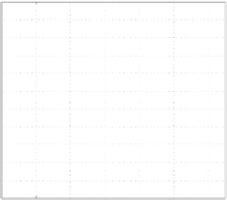
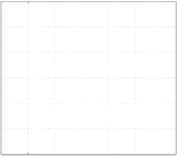
FIGURE B.2. C/A code counter output. (a) A complete cycle through all indexes of the
code. (b) The first samples of the counter output. The initial value of the counter is the
PRN code phase. In this case, the code phase is 51.
frequency of 1.023 MHz corresponding to the chipping rate of the C/A code. This
pulse is used as input to a counter.
This counter is designed to count from 0 to 1022, referring to the 1023 chips in
one PRN sequence. The counter increases its value each time a falling edge occurs
in the pulse signal, that is, with a frequency of 1.023 MHz. The initial value of the
counter is set by the PRN code phase, which is provided to the simulation as a
parameter. The PRN code phase shifts the time alignment of the PRN code. Fig-
ure B.2 shows the output from the counter. These plots are made from a simulation
with a sampling frequency of 12 MHz. A sampling frequency of 12 MHz causes
12,000 samples to last 1 ms, corresponding to one complete PRN code period.
Figure B.2a shows the output of the counter in a complete PRN code period. At
sample zero the output of the counter corresponds to the PRN code phase. When
the output reaches 1022 at approximately sample 11,000, the output is reset to its
initial value 0. Figure B.2b is a close-up on the first samples of the output from
the counter. The code phase is the initial value of the output, which in this case
is 51. This figure shows the step function of the counter. Every time a chip period
has passed the output, the counter increases by 1. When sampling with 12 MHz,
a chip period of 1 ms/1023 lasts approximately 12 samples.
The output from the counter is provided as input to the next block of the C/A
code generation part. This block is a so-called look-up table which is actually just
an array indexed by the input to the block. In this case, the look-up table is a
two-dimensional array containing the 32 possible PRN codes; see Section 2.3 for
details on PRN codes. The first dimension indicates which of the 32 PRN codes
should be used. This is the satellite supplied to the simulation. The second dimen-
sion indicates which of the 1023 chips that should be accessed. This is the input to
the look-up table block. In this case, the array is input to the simulation from the
MATLAB workspace. That is, before starting the simulation, the array with the
PRN codes has to be generated. The implementation of the PRN code generator
is described in Section 6.2. The resulting C/A code signal is shown in Figure B.3.


Search WWH ::

Custom Search