Global Positioning System Reference
In-Depth Information
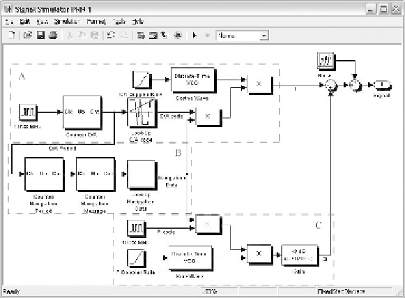
FIGURE B.1. The complete GPS signal simulator for one satellite implemented in
Simulink. Part A generates the C/A code, Part B contains the navigation data generation,
and Part C generates the simplified P(Y) code.
The MATLAB tool Simulink was chosen as the development tool for the GPS
signal simulator. The main reason for this choice is that Simulink has a very in-
tuitive user interface combined with its numerous features. One important feature
in this case is that Simulink works perfectly together with ordinary
M
-files.
The Simulink implementation is a two-level design. The upper level is where
each satellite contributing to the resulting signal is initialized. This is also where
the data file in which the data should be saved is defined. The lower level is the
implementation of each satellite. This is where the signal originating from each
satellite is generated. The signals should include the following four components:
-
C/A code
-
Navigation data
-
P(Y) code
-
Noise.
Figure B.1 shows a screen shot of the lower level of the Simulink implementa-
tion representing the signal generation in a satellite.
The following will describe the four above-mentioned parts of the signal gen-
erator.
B.2.1 C/A Code Generation
The generation of the C/A code component of the GPS signal is marked with A
in Figure B.1. Beginning from the left side of the figure, the source of the C/A
code generator is the oscillator. This oscillator produces a squared pulse with a
Search WWH ::

Custom Search