Global Positioning System Reference
In-Depth Information
I
E
Integrate
& dump
E
I
I
P
Integrate
& dump
P
I
L
Integrate
& dump
L
Incoming
signal
PRN code
generator
Code loop
discriminator
L
Integrate
& dump
Q
L
P
Q
Integrate
& dump
Q
P
E
Integrate
& dump
Q
E
90°
NCO carrier
generator
Carrier loop
filter
Carrier loop
discriminator
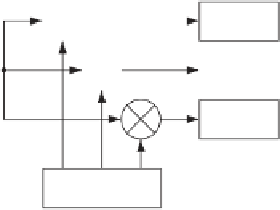
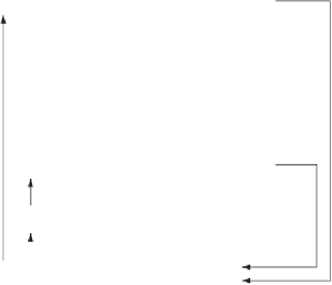
FIGURE 7.20. The block diagram of a complete tracking channel on the GPS receiver.
we obtain ranging errors
τ
in the interval
±
7
.
5m; for
δ
in the range 157-317 m
τ
±
.
τ
the delay
is within
2
5 m. Obviously the delay range
strongly depends on
=
/
the correlator spacing
d
; some papers even mention
d
1
25. See also Winkel
(2005).
7.7
Complete Tracking Block
In the previous sections, the code tracking loop and the carrier tracking loop are
described in detail. The following describes how the code tracking loop and the
carrier tracking loop can be joined to minimize the computational load.
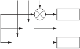
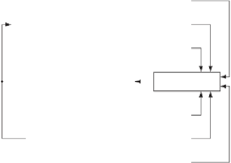
Figure 7.19 shows the code tracking loop and the carrier tracking loop com-
bined. It can be seen from the figure that the PRN code replica used to wipe off
the PRN code in the carrier tracking loop is coming from the code tracking loop.
It can also be seen that the two local carrier replicas used to wipe off the carrier
wave in the code tracking loop are coming from the carrier tracking loop. The
block diagram in Figure 7.19 contains 11 multiplications. These multiplications
are the most time-consuming operations on the block diagram.
Figure 7.20 shows an optimized version of the combined tracking loops. Here
the
I
and
Q
inputs to the phase discriminator are the
I
p
and
Q
p
correlation from
the code tracking loop. In this way the three multiplications in the Costas loop are
eliminated, and hereby the computation time is reduced.


Search WWH ::

Custom Search