Global Positioning System Reference
In-Depth Information
I
Incoming
signal
Inv Fourier
transform
Fourier
transform
| |
2
Output
Q
Complex
conjugate
90°
Fourier
transform
Local
oscillator
PRN code
generator
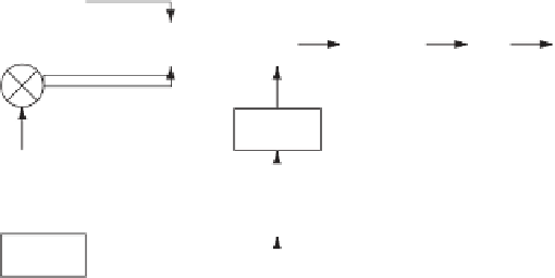
FIGURE 6.8. Block diagram of the parallel code phase search algorithm.
When the frequency domain representation of the cross correlation is found,
the time-domain representation can be found through inverse Fourier transform.
Figure 6.8 is a block diagram of the parallel code phase search algorithm. The
incoming signal is multiplied by a locally generated carrier signal. Multiplication
with the signal generates the
I
signal, and multiplication with a 90
◦
phase-shifted
version of the signal generates the
Q
signal. The
I
and
Q
signals are combined to
form a complex input signal
x
to the DFT function.
The generated PRN code is transformed into the frequency domain and the
result is complex conjugated.
The Fourier transform of the input is multiplied with the Fourier transform of
the PRN code. The result of the multiplication is transformed into the time domain
by an inverse Fourier transform. The absolute value of the output of the inverse
Fourier transform represents the correlation between the input and the PRN code.
If a peak is present in the correlation, the index of this peak marks the PRN code
phase of the incoming signal.
Compared to the previous acquisition methods, the parallel code phase search
acquisition method has cut down the search space to the 41 different carrier fre-
quencies. The Fourier transform of the generated PRN code must only be per-
formed once for each acquisition. For each of the 41 frequencies we perform
one Fourier transform and one inverse Fourier transform, so the computational
efficiency of the method depends on the implementation of these functions. The
accuracy of the parameters estimated by this acquisition method regards the fre-
quency similar to the serial search method. The PRN code phase, however, is
more accurate compared to the other methods as it gives a correlation value for
each sampled code phase. That is, if the sampling frequency is 10 MHz, a sampled
PRN code has 10,000 samples, so the accuracy of the code phase can have 10,000
different values instead of 1023.
In the same way as with the other acquisition methods, the implementation of
this one is straightforward, as it can be implemented directly based on the block
diagram shown in Figure 6.8.
(
n
)
=
I
(
n
)
+
jQ
(
n
)


Search WWH ::

Custom Search