Hardware Reference
In-Depth Information
Discussion
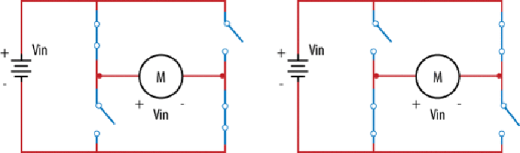
The H-bridge provides a simple way to switch the leads on a motor so that it will reverse
directions.
Figure 4-5
shows how an H-bridge works.
Figure 4-5. H-bridge schematic
The four switches connected to the motor (the big
M
in the center of
Figure 4-5
) are the H-
bridge. In the left diagram, two switches are closed, connecting the left terminal of the mo-
tor to the plus voltage and the right terminal to the ground. This makes the motor rotate in
one direction. The diagram on the right shows the other two switches closed, and the plus
and grounds are connected to the opposite terminals, making the motor spin the other way.
In the code,
in1
and
in2
are used to control each pair of switches. (The L293D has four
sets of these switches, but we are using only two pairs.) So, to turn clockwise, set
in1
HIGH
and
in2 LOW
. To go counter-clockwise, set them the opposite way:
function
clockwise
() {
b
.
digitalWrite
(
in1
,
b
.
HIGH
);
b
.
digitalWrite
(
in2
,
b
.
LOW
);
}
function
counterClockwise
() {
b
.
digitalWrite
(
in1
,
b
.
LOW
);
b
.
digitalWrite
(
in2
,
b
.
HIGH
);
}