Hardware Reference
In-Depth Information
Discussion
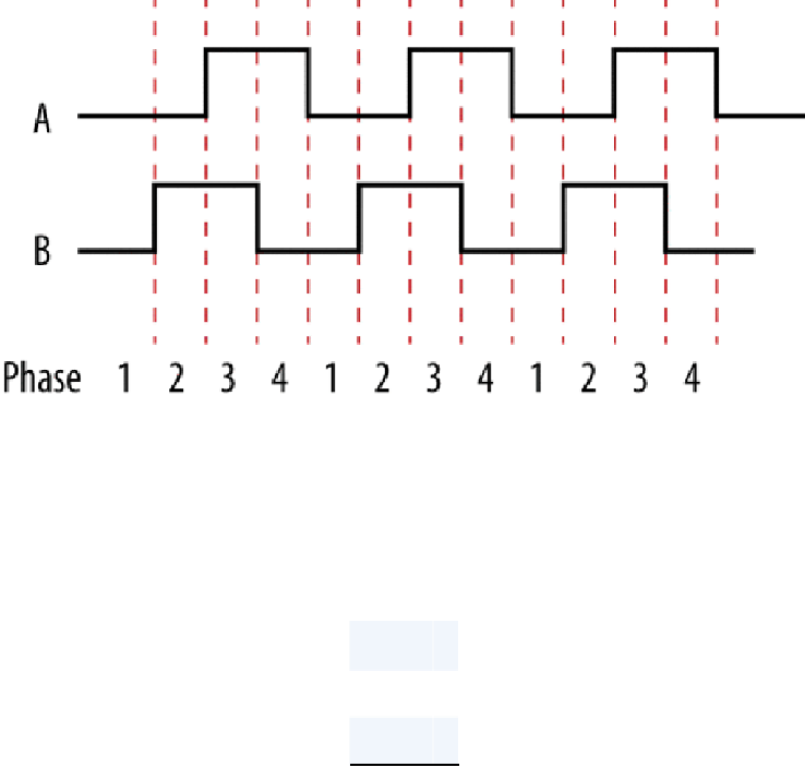
Figure 2-15
shows the sequence of pulses that occur when the encoder is turned in one dir-
ection (either clockwise or counter-clockwise, depending on the encoder).
Figure 2-15. Pulses from a quadrature encoder
When rotating clockwise, the outputs are as follows:
Phase A B
1
0 0
2
0 1
3
1 1
4
1 0
When rotating counter-clockwise, the outputs are as follows: