Agriculture Reference
In-Depth Information
area toward the lower elevations below. Figure 11.23 and Figures 11.24-A
and 11.24-B are diagrams showing how these two goals are graphically por-
trayed. The assumption here is that one of the design intentions is to create
a level area that is to remain dry. That is, an area where surface waters are
directed away, so as not to allow water to flood the structure, in the case
of a residence, school, or other building. Seems a reasonable goal. Think of
Figure 11.24 as representing a signature landform a designer can employ in
solving many grading and surface drainage situations.
Now let's look a little more closely
at the various elements involved in
creating a level area on sloping ground.
Considering Figure 11.25, let's look at
the specific contour grading details
commonly used to create a building
pad with swales. Notice in this exam-
ple that the ground is sloping from the
bottom of the figure, beginning with
contour 35 downward toward contour
27. Area E is the general area in which
we want to create a level area. This
could be for a building or a site for
a group picnic area. Area E could be
graded level or slightly sloping, perhaps
at 1 or 2 percent toward contour 31. We
might also want to set the elevation
of the level area. Elevation 31.5 would
be a good starting elevation. If we use
31.5, we next need to establish the ele-
vation of point A (the beginning of the
swale we will create to direct water
runoff away from pad). The elevation
should be lower than 31.5, somewhere
between, say, 31.4 and the next lowest
contour, which is 31. A good average
would be 31.25; that way, surface water
L e v e l A r e a
1 0 6 . 5
L e v e l A r e a
1 0 6 . 5
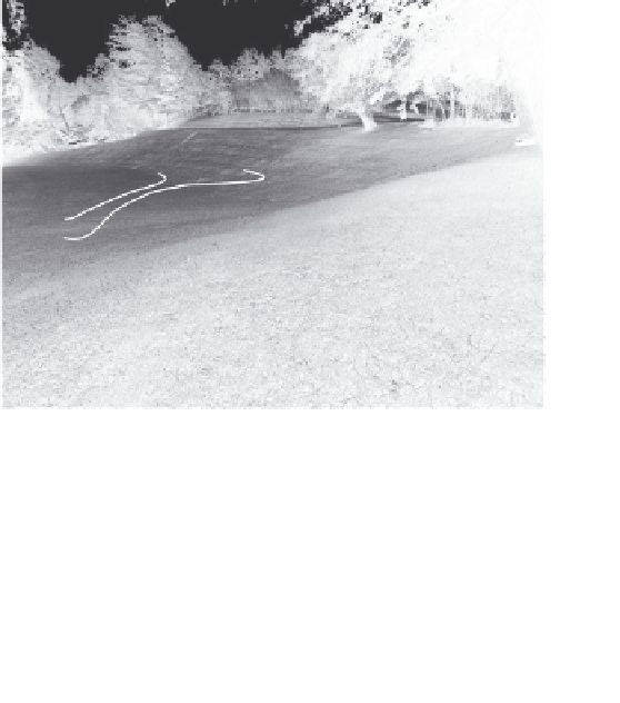
Figures 11.24-a and Figure 11.24-B
Oblique plan view depict-
ing the grading plan signature for creating a building pad. The
same plan view superimposed over a photograph of the actual
site to better visualize the form the grading signature takes for
creating a building pad and directing surface runoff away from
the area.