Agriculture Reference
In-Depth Information
G
TW
C
G
TW
E
5%
E
B
A
2%
1%
D
A
D
1%
Catch Basin/
Lowest Elevation
C
A
B
A
4” Rise
Typical
s
1
1%
A
1%
A
Figure 10.4
Stairs used as terraces in an informal student
gathering area on the Cal Tech campus in Pasadena, CA
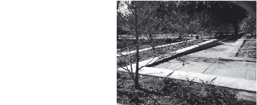
Figure 10.5
A wheelchair-accessible walk at the UCLA
campus, composed of several ramp sections with land-
ings spaced no greater than 20 feet apart. This ramp was
designed before handrails were required. A similar ramp
built today would include handrails.
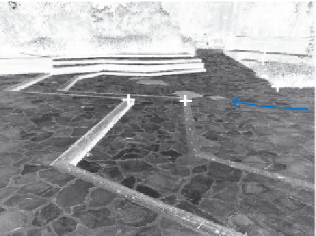
Figure 10.6 shows a more complex ramp design providing access by
means of a switchback ramp from an upper garden area to a lower plaza
and walkway. The items marked with an A indicate where spot eleva-
tions are necessary; B items are arrows showing the direction of slope
and also noting the percent of slope; and items marked C approximate
landing sections that would be sloped at 1 percent and are required and
spaced at intervals to meet wheelchair-access design standards.
3. Walls and fences:
The finished elevation of the top of walls, with spot
elevations shown at top and bottom of each stepped wall section. In the
case of walls or fences that are meant to slope at the top, a spot eleva-
tion should be noted at the beginning and end of each sloping surface.
Spot elevations were used to establish the height of walls shown in
Figure 10.7. Typically spot elevations are provided at the top and bottom
of a wall. In addition to the grading plan prepared for this Scottsdale
terrace garden, technical elevations were included in the construc-
tion documentation, showing all dimensions of the walls, with key
wall heights and their elevations indicated and coordinated with the
site-grading plan. The location and dimensions of the light fixtures (item
B) and the window cutout (item A) on the back wall also were shown in