Java Reference
In-Depth Information
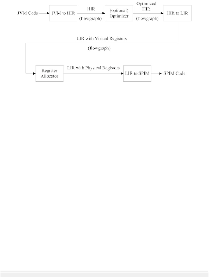
FIGURE 6.6 Phases of the JVM-to-SPIM translator.
plicit virtual registers to the operands of the instructions; there is no limit to the number
of virtual registers used. Following Wimmer, we call this a low-level intermediate represen-
tation (LIR). The instructions are very close to the instructions in our target instruction
set, SPIM.
In the fourth phase, we perform register allocation. The thirty-two physical registers in
the MIPS architecture (and thus in SPIM) are assigned to take the place of virtual registers.
Register allocation is discussed in Chapter 7.
In the fth and nal phase, we generate SPIM code|our goal.
The names of all classes participating in the translation from JVM code to SPIM code
begin with the letter
N
(the N stands for Native). The translation is directed by the driver,
NEmitter
; most of the steps are directed by its constructor
NEmitter()
.
NEmitter()
iterates through the classes and methods for each class, constructing the
control-flow graph of HIR instructions for each method, doing any optimizations, rewriting
the HIR as LIR and performing register allocation.
SPIM code is emitted by the driver (
Main
or
JavaCCMain
) using
NEmitter
's
write()
method.
6.3.2 HIR Control-Flow Graph
The Control-Flow Graph
The first step is to scan through the JVM instructions and construct a flow graph of basic
blocks. A basic block is a sequence of instructions with just one entry point at the start and
one exit point at the end; otherwise, there are no branches into or out of the instruction
sequence.
To see what happens here, consider the JVM code for the method
computeIter()
from
our
Factorial
example:
publicstaticintcomputeIter(int);
Code:
Stack=2,Locals=2,Args_size=1
0:const_1
1:istore_1
2:iload_0
3:iconst_0


Search WWH ::

Custom Search