Environmental Engineering Reference
In-Depth Information
(a)
Transect orientation and lay-out (Random compass direction)
100m
10 m
10 m
5m
Seaward
edge
10m
5m
5m
10m
10m
Baseline
0.2 - 2.7km
5m
5m
10m
5m
10m
10m
10 m
20m
20m
(b)
10m
5m
0.5m
0.5m
Baseline (transect axis)
1m
1m
1m
5m
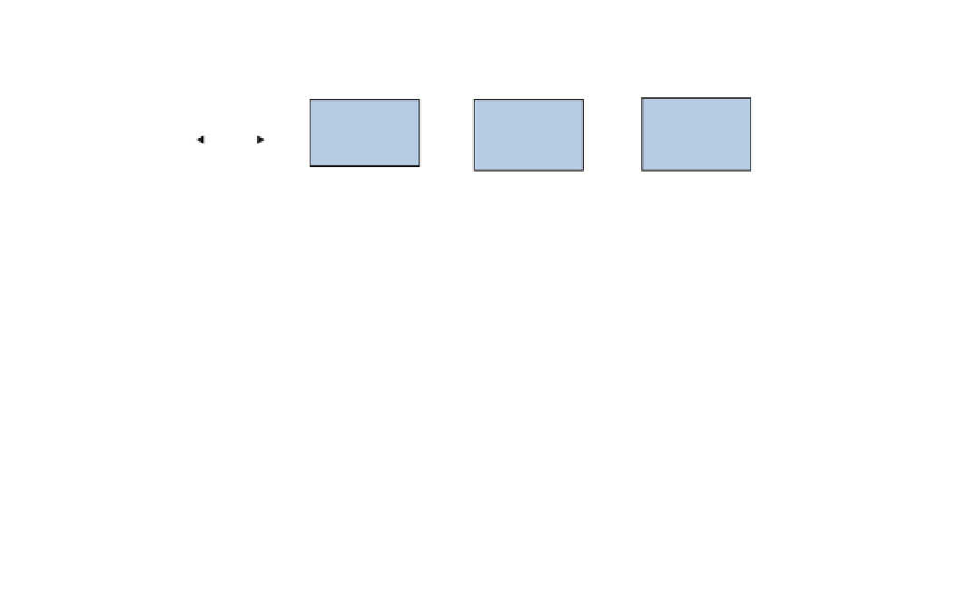
Fig. 2
a Schematic layouts of mangrove forest stands permanent sample plots and, b roots and sapling inventories (After Ajonina
2008
)
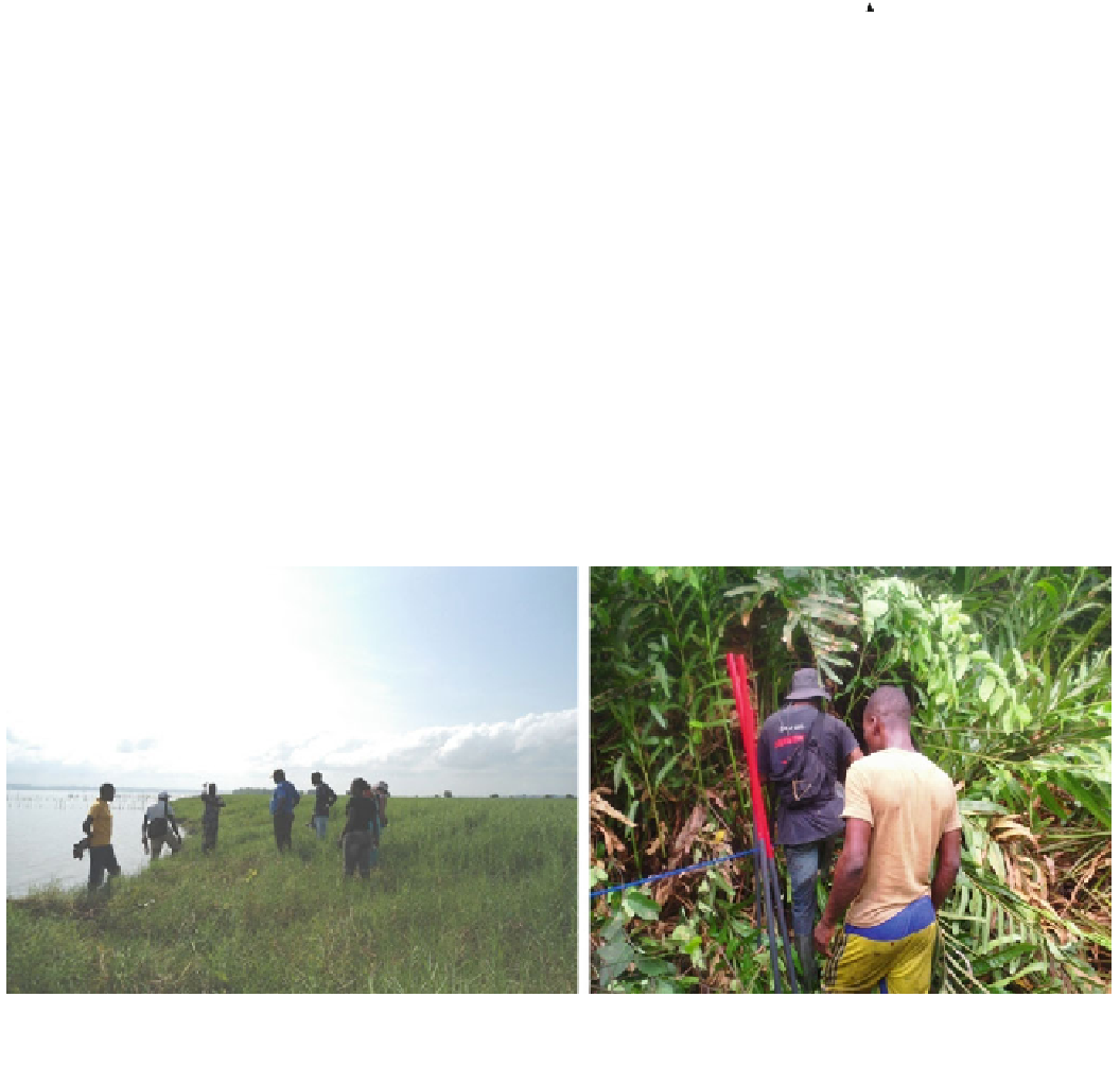
Fig. 3
Permanent transect layout: Kpétou village site (transect 1) with non-mangrove woody vegetation (left) and degraded mangrove
vegetation (Photos Diyouke Eugene and Gordon Ajonina 2012)
ignition (LOI) and cooled in desiccators before reweighing.
The weight of each ashed sample was recorded and used to
calculate organic concentration (OC). Total soil carbon was
calculated as
The total soil carbon pool was then determined by sum-
ming the carbon mass of each of the sampled soil depths.
Data Analysis and Algometric Computations
¼ bulk density
tonnes
=
ha
1
g
=
cm
3
Soil C
soil depth interval
c
ðÞ
% C
ð
2
Þ
Field data were organized into various filing systems for
ease
of
analysis
and
presentation.
Both
structural
and


Search WWH ::

Custom Search