Graphics Reference
In-Depth Information
For each patch, a quadtree structure is built using the function R(
p
). The bound-
ary curves for trimming regions for each patch were then polygonized using this struc-
ture. These curves consisted of parts of trimming curves and possibly parts of
boundary curves for patches. Cracks were prevented by defining a single polygonized
curve for a common boundary. A sufficient number of vertices were then placed
randomly in the interior of all the trimming regions. This number was determined by
making an estimate of the number of vertices in an admissible triangulation. Finally,
a relaxation method was used on the selected vertices to move them into vertices of
an admissible triangulation. The method was different from the one used in [ShiG95]
because the attraction-repulsion force approach was considered to have drawbacks
and also could not guarantee that one got permissible triangles without additional
testing. Instead, a constrained Delaunay triangulation of the interior vertices and the
vertices of the trimming curves and any boundary curves was computed after each
relaxation step and checked for admissibility. The relaxation step involved moving ver-
tices if they belonged to edges that were too long or too short. Each offending edge
determined a translation of the vertex and the actual move of the vertex was the vector
sum of the translation vectors defined by all the incident edges. Care had to be taken
so as not to move outside of the trimming region.
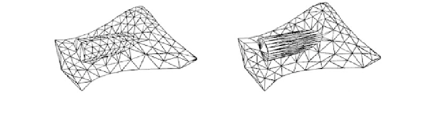
Anglada et al. ([AnGC99]) describe another variant of the algorithm in [VigB95].
The main difference between the two is that a different and often smaller set of
triangles is generated. In [AnGC99] the triangles are determined using directional
bounds. One takes directional aspects of curvature into account, so that if the curva-
ture is small in one direction and larger in another one, then one get elongated tri-
angles aligned with the first direction. For example, in the extreme case of a cylindrical
shaped surface one would get thin triangles aligned with the axis of the cylinder and
as long as it. Figure 14.16(a) and (b) show the difference in results after applying the
algorithm in [VigB95] and [AnGC99], respectively.
The paper by Cho et al. ([ChPP98]) takes quite a different approach to the trimmed
surface problem. One problem encountered by many of the algorithms described
above is that they triangulate a surface
S
by triangulating the domain of a parame-
terization p(u,v). Even if one makes sure that the resulting triangulation is a good
enough approximation, the map p(u,v) from parameter space to
R
3
inevitably intro-
duces distortions in the triangles since it is not an isometry. The approach suggested
in [ChPP98] is to reparameterize the surface so that the new parameterization is close
(a)
(b)
Figure 14.16.
Results of the algorithms in Vigo, M., et al. “Piecewise Linear Approxi-
mation of Trimmed Surfaces,” in [HaFN95], 341-356 and Anglada, M.V., et al., “Direc-
tional Adaptive Surface Triangulation,” CAGD,
16
(2), February 1999, 107-126.