Graphics Reference
In-Depth Information
Step 1:
List of
polygons
Shape to
world coords
Vertex intensity computations
using radiosity method
Æ
Æ
Step 2:
Polygons in world coords
with intensity data
Trivial
reject/accept
World to
hclip coords
Æ
Æ
Clipping
To clip coords in
[0,1]¥[0,1]¥[0,1]
To frame and
Z-buffer
Screen
Æ
Æ
Æ
Æ
(a)
Radiosity and Gouraud shading
Æ
Æ
Æ
List of
polygons
Shape to
world coords
Ray tracing
Screen
(b)
Ray tracing
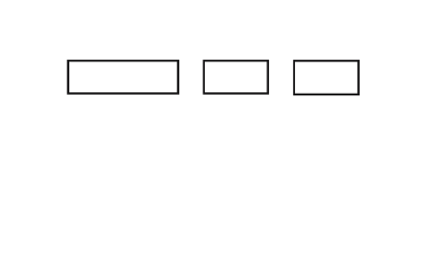
Figure 9.19.
Global illumination rendering pipelines.
values, the light direction vectors, etc., on which illumination computations are based,
must all be in world or camera coordinates.
As a third example of the rendering pipeline, suppose that one were to use a list
priority algorithm such as the BSP algorithm and Phong shading. The pipeline will
be similar to the one shown in Figure 9.18(b), but we do not need a Z-buffer here
because polygons are ordered by depth and we can use a painter's algorithm.
Global Illumination Pipelines.
In the case of radiosity and, say, Gouraud shading
we first convert objects to world coordinates and precompute the view-independent
vertex intensities. This new data is then fed into a standard rendering pipeline, which
no longer needs to do any lighting computations. See Figure 9.19(a).
The ray-tracing rendering pipeline is the easiest of them all. It is shown in Figure
9.19(b). We simply convert all objects into world coordinates and then do the ray
tracing for each pixel on the screen.
9.10
Selecting a Color Palette
After the pixel data has been generated for an image, one is sometimes faced with one
last decision, namely, choosing a
palette
(an indexed collection of colors). The problem
is that there may be a limit to how many colors a graphics system can display at any
one time and the image may contain more colors than that. This is no longer such a