Graphics Reference
In-Depth Information
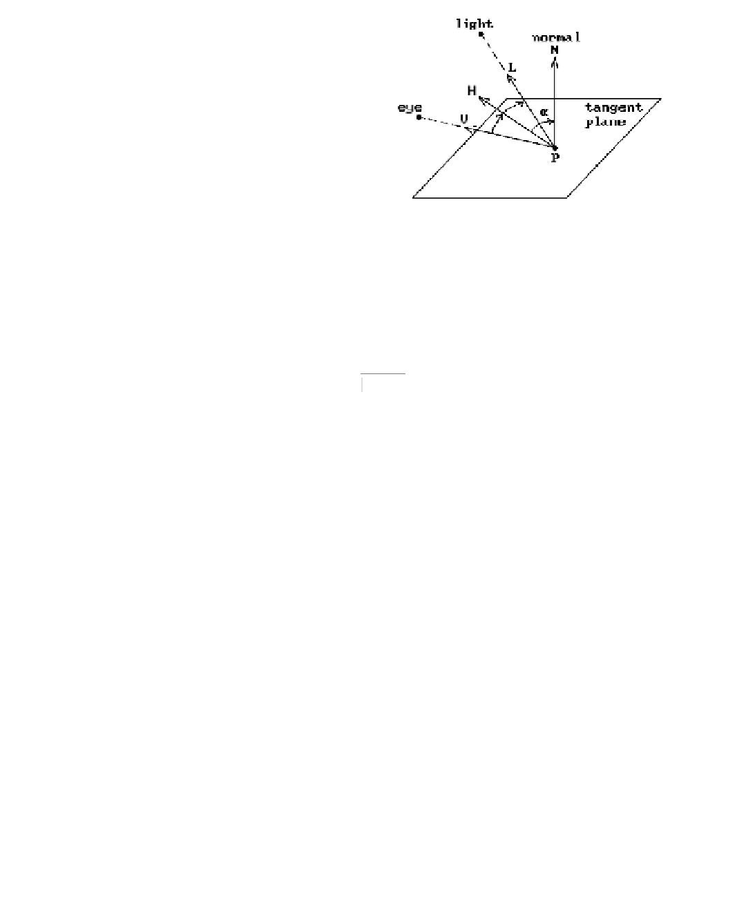
Figure 9.1.
Some basic notation.
The following notation will be used throughout this chapter. See Figure 9.1. At
each point
p
of a surface the
unit
normal to the tangent plane at that point will be
denoted by
N
. The vectors
V
and
L
are the
unit
vectors that point to the eye (or
camera) and the light, respectively. It is convenient to define another
unit
vector
H
which is the bisector of
V
and
L
, that is,
VL
VL
+
+
H
=
.
The angle between
H
and
N
will be denoted by a.
The simplest reflectance model ([Bouk70]) takes only ambient and diffuse light
into account. The ambient component of the intensity is assumed to have the form
() ()
,
I
ll
k
a
where I
a
(l) is the ambient light intensity at wavelength l and k
a
(l) Π[0,1] is the
ambient reflection coefficient
, which is the proportion of ambient light that is reflected.
The diffuse component is assumed to have the form
() ()
,
I
ll
kr
p
d
d
where I
p
(l) is the intensity of the point light source reaching the point
p
, k
d
(l) Π[0,1]
is the
diffuse reflection coefficient
, which is a constant that depends on the material,
and r
d
is the
diffuse reflectance factor
. The factor r
d
is computed from Lambert's law
for ideal diffuse reflectors which states that they will diffuse incident light
equally in
all directions
. Consider Figure 9.2. An area A
1
of light incoming along a direction
L
will shine on an area A
2
in the plane with normal
N
. If q is the angle between
N
and
L
, then it is easily shown that
A
A
1
2
=
cos
q
=
NL
∑
.