Graphics Reference
In-Depth Information
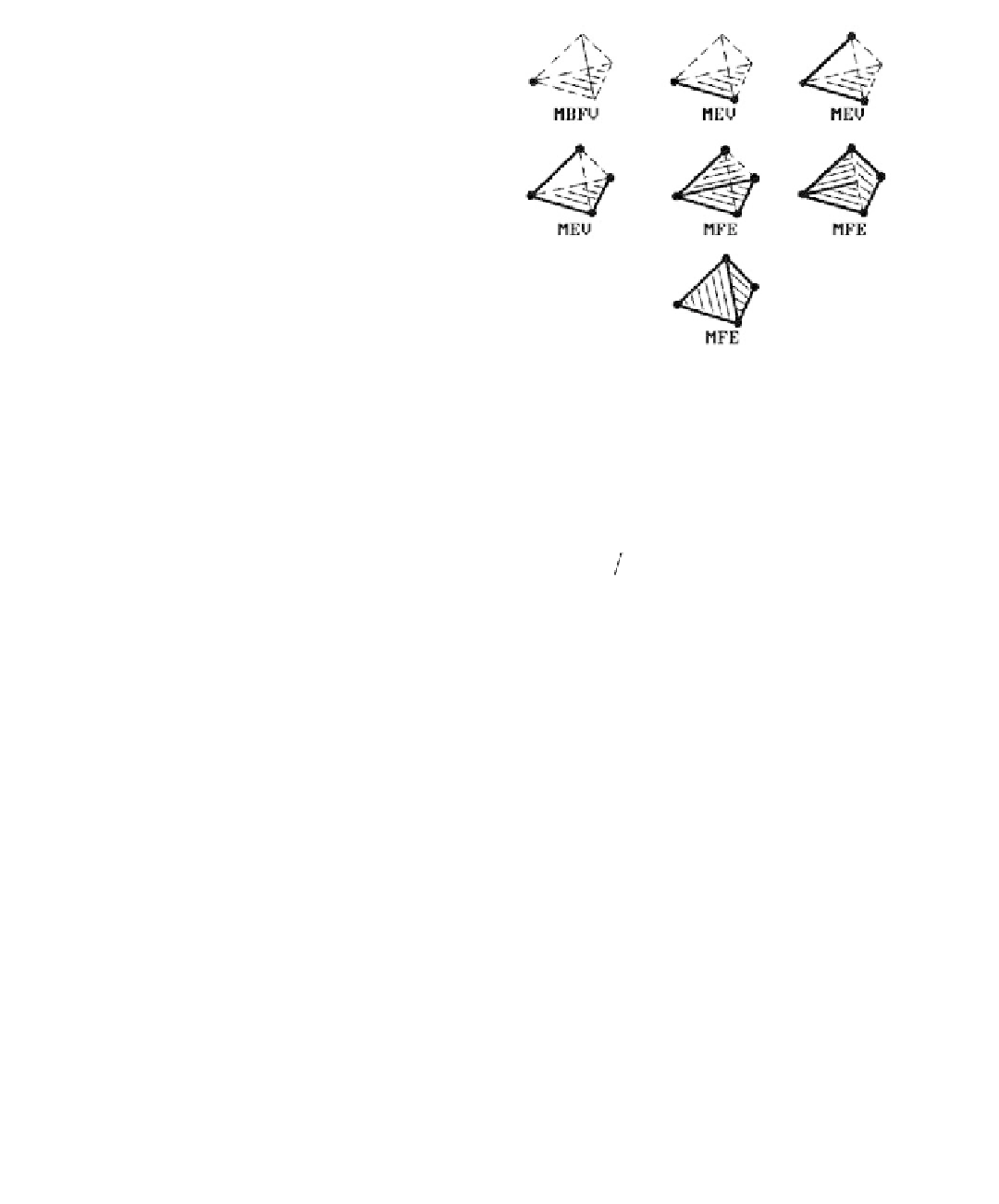
Figure 5.15.
Building a tetrahedron with
Euler operations.
Baumgart's winged edge representation (see Section 5.8.1) or some variant of it, so
that this is what these operators modify.
Historically, Euler operators were given cryptic mnemonic names consisting of
letters. A few of these are shown below along with their meanings:
M
-
make
K
-
kill
L - loop
V
-
vertex
E
-
edge
F
-
face
B
S
-
body solid
Using that notation, three typical operators were:
MEV
-
-
-
make ede and vertex
MFE
make face and edge
MBFV
make body, face, and vertex
Figure 5.15 shows how one could create a solid tetrahedron using these operators.
The operators create the appropriate new data structure consisting of vertices,
edges, faces, and solids and merge it into the current data structure. Along with each
Euler operator that creates vertices, edges, or faces, there are operators that delete or
kill them. This enables one to easily undo operations, a very desirable feature for a
modeler.
There are good references for implementing modelers based on Euler operations.
One is the topic by Mäntylä ([Mant88]), which describes a modeling program
GWB (the Geometric WorkBench). Another is the topic by Chiyokura ([Chiy88]),
which describes the modeling program DESIGNBASE. Euler operations were
originally defined only for polyhedra but were extended to curved surfaces by
Chiyokura.
To summarize, modelers based on Euler operations are really “ordinary” b-rep
modelers except that the objects and boundary representations that can be built are
constrained by the particular Euler operators that were chosen, so that they at least
have combinatorial validity. The Euler operators are flexible enough though so that