Graphics Reference
In-Depth Information
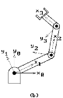
Figure 4.25.
Two-dimensional robot arm geometry.
and q
i
. Our discussion above basically showed how the latter are derived from the
former. One can also show that the link parameters completely define the frames. In
practice it is easier for a user to manipulate the link parameters and so the usual
problem is to find the frames given their values. As another example, consider a two-
dimensional robot with three links and revolute joints. We can think of this as a special
case of the general one where all the z-axes of the frames point in the same direction
and all the a
i
and d
i
are zero. Figure 4.25(a) shows the link parameters and Figure
4.25(b), the associated frames.
As one can see, frames play a role in defining the state of a robot, but how are
they used to solve problems? Well, the forward kinematic problem is to find the tool
frame (“where the tool is”) given the link parameters. This problem will be solved if
we can determine the transformation T
n
, which, given the coordinates of a point
p
in
F
n
coordinates, finds the coordinates of
p
with respect to F
0
. Let dT
i
, 0 < i £ n, denote
the transformation that maps coordinates relative to F
i
to coordinates relative to
F
i-1
. It follows that
T T T
=
o Lo
T
.
(4.21)
n
n
1
2
The dT
i
are relatively easy to compute from the link parameters because they are the
composition of four simple maps.
The Computation of dT
i
and Its Homogeneous Matrix dM
i
.
Let T
i
(
z
i
, d
i
) denote
the translation with translation vector d
i
z
i
. Its homogeneous matrix is
1000
01 0 0
00 1 0
00
Ê
ˆ
Á
Á
Á
˜
˜
˜
Ë
¯
d
i
1