Graphics Reference
In-Depth Information
4.7
Putting It All Together
We are finally ready to put all the pieces together. See Figure 4.1 again. Starting with
some shape we are initially in shape coordinates. We then
(1) transform to world coordinates
(2) transform from world to homogeneous clip coordinates by composing
T
worÆcam
and T
camÆhclip
(3) clip
(4) project (x,y,z,w) down to (x/w,y/w,z/w) in the unit cube of clip space with T
proj
(5) map the unit square in the x-y plane of clip space to the viewport
(6) map from the viewport to pixel space
With respect to (4), note that using a front clipping plane does have the advantage
that we do not have to worry about a division by zero. Almost, but not quite. There
is the very special case of (0,0,0,0) that could occur and hence one needs to check for
it (Exercise 4.7.1). It would be complicated to eliminate this case.
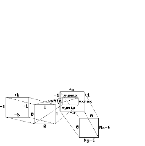
Also, because of the clipping step, Blinn suggests a more complete version of the
window-to-pixel map than shown in Figure 4.9. See Figure 4.13. The square [0,1] ¥
[0,1] represents the clipping. This allows one to handle the situation shown in Figure
4.14, where the viewport goes outside the valid NDC range quite easily. One pulls back
the clipped viewport
[
]
¥
[
]
ux
min,
ux
max
uy
min,
uy
max
to the rectangle
[
]
¥
[
]
wx
min,
wx
max
wy
min,
wy
max
and then uses that rectangle as the window. Only the transformation T
camÆhclip
needs
to be changed, not the clipping algorithm.
Blinn's approach is nice, but there may not be any need for this generality. A much
simpler scheme that works quite well is to forget about the NDC by incorporating the
hardware aspect ratio r
h
into the window size. Let
Figure 4.13.
From window to pixel
coordinates.