Graphics Reference
In-Depth Information
4.5
The Clip Coordinate System
Once one has transformed objects into camera coordinates, our next problem is to
clip points in the camera coordinate system to the truncated pyramid defined by
the near and far clipping planes and the window. One could do this directly, but we
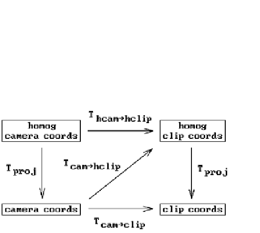
prefer to transform into a coordinate system, called the
clip coordinate system
or
clip
space
, where the clipping volume is the unit cube [0,1] ¥ [0,1] ¥ [0,1]. We denote the
transformation that does this by T
camÆclip
. There are two reasons for using this
transformation:
(1) It is clearly simpler to clip against the unit cube.
(2) The clipping algorithm becomes independent of boundary dimensions.
Actually, rather than using these coordinates we shall use the associated homogeneous
coordinates. The latter define what we shall call the
homogeneous clip coordinate
system
or
homogeneous clip space
. Using homogeneous coordinates will enable us to
describe maps via matrices and we will also not have to worry about any divisions by
zero on our way to the clip stage. The map T
camÆhclip
in Figure 4.1 refers to this
camera-to-homogeneous-clip coordinates transformation. Let T
hcamÆhclip
denote the
corresponding homogeneous-camera-to-homogeneous-clip coordinates transforma-
tion. Figure 4.10 shows the relationships between all these maps. The map T
proj
is the
standard projection from homogeneous to Euclidean coordinates.
Assume that the view plane and near and far clipping planes are a distance d, d
n
,
and d
f
in front of the camera, respectively. To describe T
camÆhclip
, it will suffice to
describe T
hcamÆhclip
.
First of all, translate the camera to (0,0,-d). This translation is represented by the
homogeneous matrix
10 0 0
01 0 0
00 1 0
00
Ê
ˆ
Á
Á
Á
˜
˜
˜
M
tr
=
.
Ë
¯
-
d
1
Figure 4.10.
The camera-to-clip
space transformations.