Graphics Reference
In-Depth Information
Æ
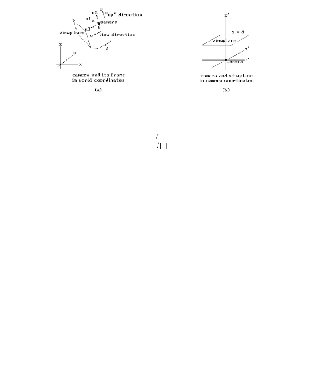
Figure 4.3.
The camera coordinate system.
uvv
uww
uuu
=
=
=¥.
3
(4.1)
2
1
3
2
These last two axes will be the same axes that will be used for the viewport. There
were only two possibilities for
u
1
in equations (4.1). Why did we choose
u
3
¥
u
2
rather
than
u
2
¥
u
3
? Normally, one would take the latter because a natural reaction is to
choose orientation-
preserving
frames; however, to line this x-axis up with the x-axis
of the viewport, which one always wants to be directed to the right, we must take the
former. (The easiest way to get an orientation-preserving frame here would be to
replace
u
3
with -
u
3
. However, in the current situation, whether or not the frame is
orientation-preserving is not important since we will not be using it as a motion but
as a change of coordinates transformation.)
Although an up direction is needed to define the camera coordinate system, it is
not always convenient to have to define this direction explicitly. Fortunately, there is
a natural default value for it. Since a typical view is from some point looking toward
the origin, one can take the z-axis as defining this direction. More precisely, one can
use the orthogonal projection of the z-axis on the view plane to define the second axis
u
2
for the camera coordinate system. In other words, one can define the camera frame
by
uvv
uww
=
=
3
(
)
,
where
we euu
=
-
∑
(4.2)
2
3
3
3
3
uuu
=¥
.
1
3
2
As it happens, we do not need to take the complete cross product to find
u
1
, because
the z-coordinate of
u
1
is zero. The reason for this is that
e
3
lies in the plane gen-
erated by
u
2
and
u
3
and so
u
1
is orthogonal to
e
3
. It follows that if
u
3
= (u
31
,u
32
,u
33
)
and
u
2
= (u
21
,u
22
,u
23
), then