Graphics Reference
In-Depth Information
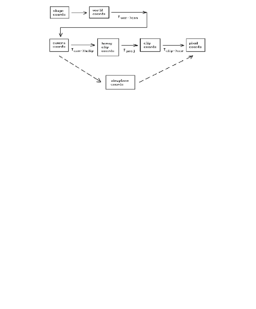
Figure 4.1.
The coordinate system pipeline.
three-dimensional environment. Section 4.10 discusses some advantages and dis-
advantages to using homogeneous coordinates in computer graphics. Section 4.11
explains how OpenGL deals with projections. The reconstruction of objects and
camera data is the subject of Section 4.12 and the last graphics pipeline related topic
of this chapter. The last two sections of the chapter are basically further examples of
transformations and their uses. Section 4.13 takes another look at animation, but from
the point of view of robotics. This subject, interesting in its own right, is included
here mainly to reinforce the importance of understanding transformations and
frames. Next, Section 4.14 explains how quaternions are an efficient way to express
transformations and how they are particularly useful in animation. We finish the
chapter with some concluding remarks in Section 4.15.
4.2
From Shape to Camera Coordinates
This section describes the first three coordinate systems in the graphics pipeline. In
what follows, we shall use the term “shape” as our generic word for a geometric object
independent of any coordinate system.
The World Coordinate System.
This is the usual coordinate system with respect to
which the
user
defines objects.
The Shape Coordinate System.
This is the coordinate system used in the actual
definition of a shape. It may very well be different from the world coordinate system.
For example, the standard conics centered around the origin are very easy to describe.
A good coordinate system for the ellipse in Figure 4.2 is defined by the indicated frame
(
u
1
,
u
2
,
p
). In that coordinate system its equation is simply