Information Technology Reference
In-Depth Information
4.
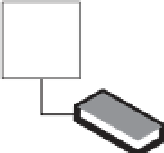
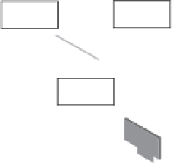
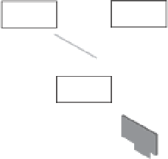
The target host (esxi-04a) reads the addresses in the memory bitmap i le and requests the
contents of those addresses from the source (esxi-03a). See Figure 12.4.
Figure 12.4
In step 4 in a vMo-
tion migration,
the actual memory
listed in the bitmap
fi le is fetched from
the source to the
destination (dirty
memory).
pod-1-blade-5.v12nlab.net
pod-1-blade-7.v12nlab.net
VM1
(Quiesced,
inactive)
VM1
(inactive)
vSwitch0
vSwitch2
vSwitch0
vSwitch2
VM port
group
VM port
group
ESXi mgmt
network
ESXi mgmt
network
vSwitch1
vSwitch1
VMkernel
port
VMkernel
port
VM1
dirty
memory
fetch
Physical switch
vSphere Client
5.
After the contents of the memory referred to in the memory bitmap i le are transferred
to the target host, the VM starts on that host. Note that this is not a reboot—the VM's
state is in RAM, so the host simply enables it. At this point a Reverse Address Resolution
Protocol (RARP) message is sent by the host to register its MAC address against the
physical switch port to which the target ESXi host is connected. This process enables
the physical switch infrastructure to send network packets to the appropriate ESXi host
from the clients that are attached to the VM that just moved.
6.
After the VM is successfully operating on the target host, the memory the VM was using
on the source host is deleted. This memory becomes available to the VMkernel to use as
appropriate, as shown in Figure 12.5.