Information Technology Reference
In-Depth Information
Table 1 Filter and saturation
parameters
Parameter
Value
a
0
5
a
1
0.1
ʱ
1
ʲ
0.06
ʔ
100
ʻ
0.9
r
1
Table 2 Parameters with
AW and no AW
compensation
Parameter
Value with AW
compensation
Value with no AW
compensation
K
c
0.0635
0.0036
˄
0.9503
33,327.8
i
˄
1
0.0005
d
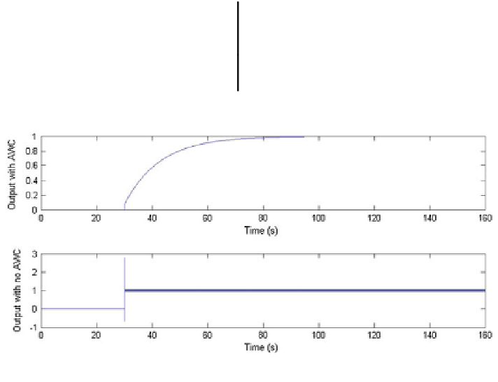
Fig. 4 System response with the IMC AWC (upper) and with no AWC (lower)
implemented where a high overshoot, a large settling time and higher oscillations
are shown proving that the system has a better performance when the anti windup
controller is implemented. These results are yielded due to the feedback compen-
sation applied to the PID controller reducing the unwanted effects produced by
windup, in comparison when there is not compensation where the system perfor-
mance is deteriorated due to the increasing in the integrator output when the input
of the system is saturated.
In Fig.
5
the input U for the system with AWC is shown where the input is
generated according to the reference signal. This signal is the non saturated signal
generated by the IMC PID AWC, so the signal follows a designated trajectory
according to the required control input necessary to control the system.


Search WWH ::

Custom Search