Information Technology Reference
In-Depth Information
ˀ
Grid
u
u
,
s
ʱ
ʸ
sc
a
b
−
1
3/2
arctan
u
s
ʲ
ʸ
s
Speed and currents measurement,
Calculation
DFIM
FABC
u
,
rc
a
b
Reference signals
u
u
rd
rq
u
r
ʱ
e
ʸ
j
Converter
r
2/3
u
r
ʲ
=
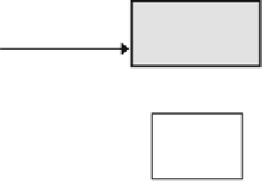
Fig. 4 The overall control scheme of the DFI-Motor
6 Simulation Results
In order to investigate the control system effectiveness, a numerical simulation has
been realized with a 4 kW DFI-Motor. Table
1
summarizes the DFI-Motor
s
parameters along with their respective values (Vidal
2004
). The performances of
the control scheme are evaluated in terms of response to speed variation, sensitivity
to external disturbances and robustness against machine parameters variations. The
design parameters are selected as:
'
c
1
¼
0
:
001
; b
¼
200
; k
1
¼
200
; c
1
¼
100
; g
1
¼
0
:
05
; k
2
¼
200
; c
2
¼
1
;
000
; g
2
¼
0
:
1
; r
1
¼
r
3
¼
0
:
1
; r
2
¼
r
4
¼
0
:
1
:
The
initial
j
1
ð
Þ
¼
j
1
ð
Þ
¼
:
h
1i
ð
Þ
¼
h
2i
ð
Þ
¼
conditions are chosen as:
0
0
0
2, and
0
0
0. The
d
1
x
1
;
ð
Þ
¼
unknown uncertainties and perturbations are selected as:
x
2
3x
2
and
d
2
x
3
;
x
ð Þ
¼4x
2
þ
2x
2
.
The fuzzy system
v
2
; C
l
T
T
h
1
w
1
ð^
z
1
Þ
has the vector
½
x
1
;
x
2
;
x
4
;
x
5
;
as input, while
T
as input. For each
variable of the entries of these fuzzy systems, as in (Boulkroune et al.
2008
), we
de
T
the fuzzy system
h
2
w
2
ð
z
2
Þ
has the state vector
½
x
1
;
x
2
;
x
3
;
x
4
;
x
5
ne three (one triangular and two trapezoidal) membership functions uniformly
distributed on the intervals
0
:
5
;
1
:
5
½
for x
2
;
x
3
, x
4
and x
5
,
150
;
150
½
for x
1
,
for
C
l
.
½
2
;
2
for
t
2
, and
½
150
;
150


Search WWH ::

Custom Search