Game Development Reference
In-Depth Information
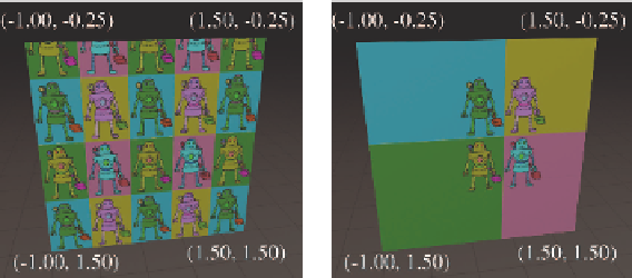
Repeat
Clamp
Figure 10.18.
Comparing repeating and clamping texture addressing modes
Let's look at some examples.
Figure 10.17
shows a single texture-
mapped quad, with different UV values assigned to the vertices. The bot-
tom of each diagram shows the UV space of the texture. You should study
these examples until you are sure you understand them.
UV coordinates outside of the range [0,1] are allowed, and in fact are
quite useful. Such coordinates are interpreted in a variety of ways. The
most common addressing modes are repeat (also known as tile or wrap) and
clamp. When repeating is used, the integer portion is discarded and only
the fractional portion is used, causing the texture to repeat, as shown in
the left side of Figure 10.18. Under clamping, when a coordinate outside
the range [0,1] is used to access a bitmap, it is clamped in range. This has
the effect of streaking the edge pixels of the bitmap outwards, as depicted
on the right side of Figure 10.18. The mesh in both cases is identical:
a single polygon with four vertices. And the meshes have identical UV
coordinates. The only difference is how coordinates outside the [0,1] range
are interpreted.
There are other options supported on some hardware, such as mirror,
which is similar to repeat except that every other tile is mirrored. (This
can be beneficial because it guarantees that no “seam” will exist between
adjacent tiles.) On most hardware, the addressing mode can be set for
the u- and v-coordinates independently. It's important to understand that
these rules are applied at the last moment, when the coordinates are used
to index into the texture. The coordinates at the vertex are not limited or
processed in any way; otherwise, they could not be interpolated properly
across the face.
Figure 10.19
shows one last instructive example: the same mesh is tex-
ture mapped two different ways.


Search WWH ::

Custom Search