Global Positioning System Reference
In-Depth Information
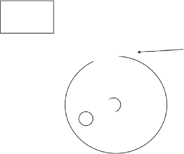
Sensing coil
Magnet
Signal processor
S
Protruding tab
N
Driveshaft
Figure 9.30
Variable reluctance rotation sensor. (
From:
[29]. © 2000 University of Calgary.
Reprinted with permission.)
integration algorithm (this concern is discussed further in the next section). Finally,
motion of the vehicle when the tires are stationary (e.g., as could occur when
the vehicle is transported with a tow truck or onboard a ferry) can also lead to
excessive positioning error; this is a second recovery mode for the sensor integration
algorithm.
Excepting these anomalies, speed determination is affected by the ability to
measure distance traveled using the circumference of the wheel. Typically, 24 to 48
pulses are generated for each wheel revolution. The scale factor that converts pulse
counts to distance traveled can be accurately calibrated at installation by driving a
known distance. However, slow variations in tire pressure can degrade the initial
calibration and, over time, affect the accuracy of the scale factor. Wheel sensors suf-
fer from the same problems described for the transmission sensors—however, with
potentially more serious error conditions. Individual wheel sensors can be used to
determine heading changes of the vehicle as well as speed. This is done by measuring
the difference in the distance traveled by each nondriven wheel, a technique known
as differential odometry. If the vehicle is making a right turn, the left wheel has to
travel farther than the right wheel to complete the turn and vice versa. Assuming
that the sensors are installed on nondriven rear wheels, the following equation can
be used to compute heading change,
∆
H
, and is illustrated in Figure 9.31:
(
)
∆
Hd dT
R
=
−
(9.19)
L

Search WWH ::

Custom Search