Global Positioning System Reference
In-Depth Information
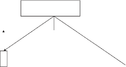
Tall building
Top view
Reflected
signal path
V
β
β
β
Vehicle
Tall building
Reflected signal
Doppler = Vcos
β
True signal
Doppler =
Vco
−β
Direct signal path
Figure 9.29
Illustration of reflected signal tracking geometry.
zero as the magnetic flux change becomes small, as illustrated in Figure 9.30. When
the motion of the protruding tab through the magnetic field becomes too slow, the
signal processor will not be able to detect a pulse, corresponding to a certain dis-
tance moved by the wheel. Depending on the specific sensor utilized and the signal
processing circuitry, speeds of 0.5 to several meters per second may be undetectable.
On the other hand, Hall-effect sensors [48], whose output is position rather than
rate sensitive, can detect vehicle speed reliably down to stationary conditions. For
this reason, Hall-effect sensors are preferred, but they are generally more expensive
to install.
Independent of the type of sensor utilized, transmission odometer-based speed
determination can be unreliable under three distinct conditions:
•
Wheel slipping;
•
Wheel skidding;
•
Vehicle motion when the tires are stationary.
The first problem can be reduced by installing sensors so they detect the motion
of the nondriven wheels (e.g., the nondriven wheels of a front-wheel drive vehicle
are the rear wheels, and vice versa). Otherwise, tire slippage can lead to gross posi-
tioning errors in the DR system, since the sensed speed will generally greatly exceed
the actual speed of the vehicle. Some slippage will occur, even with nondriven wheel
installation, but generally only during braking and cornering. The second problem,
wheel skidding, is much more difficult to solve; however, the potential for it can be
reduced but not eliminated by use of an ABS. Detection of and recovery from skid-
ding conditions should be an important consideration in the design of the sensor


Search WWH ::

Custom Search