Global Positioning System Reference
In-Depth Information
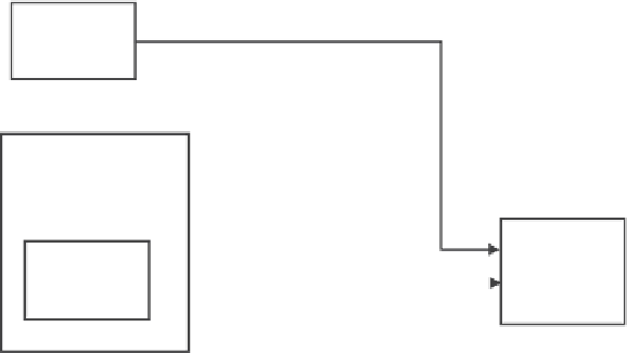
IMU
∆θ
s,
∆ν
s
3 gyros
3 accel.
GPS receiver
Channel
processor
Navigation
processor
P, V, T
and att
itude
N-state
Kalman
filter
,
ρρ
1-6 channels
P, V
Figure 9.9
Tight integration of a GPSI system.
directly to the navigation processor. In this configuration, unmodeled errors result-
ing from the GPS receiver's Kalman filter are eliminated and the system designer is
allowed to set gains as tight as possible.
In the tight integration of a GPSI system, as in most inertial systems, we utilize
the Kalman filter to estimate the error in our state, not the state itself, and use the
estimated error state vector
x
to correct the output of the navigation equations, as
shown in Figure 9.10. Also typical in the so-called tight integration of a GPSI, espe-
cially in applications where antijam enhancement of the GPS receiver is needed, is
some form of tracking loop aiding. As introduced in Section 9.2.1, this aiding can
occur at both carrier and code loop levels. Aiding the code loop is most commonly
implemented. Aiding the phase lock loop within the receiver is much more difficult.
The difficulty is obviously driven by the relatively tight requirements, from a navi-
gation perspective, for maintaining phase lock on the carrier. Phase lock generally
requires that tracking loop error is less than a fraction of the carrier cycle. For
$
GPS
receiver
.
,
ρρ
Kalman filter
Measurement
processing
P, V
y
(Observation)
,
∆θ ∆ν
x
(Error states)
Navigation
equations
Inertial
sensors
P,V,Att
Corrected
position (P),
velocity (V)
and attitude
Figure 9.10
GPSI functional block diagram.


Search WWH ::

Custom Search