Global Positioning System Reference
In-Depth Information
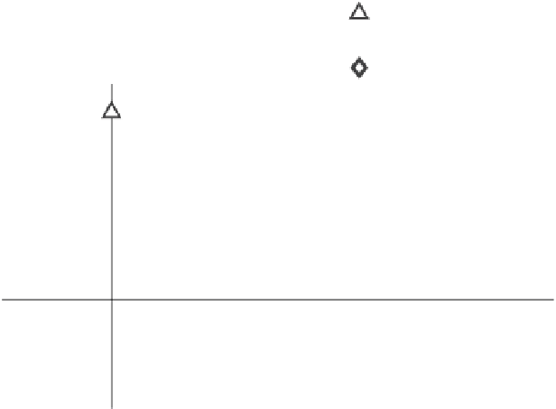
BPSK-R(1), 4 MHz
BPSK-R(1), 24 MHz
BPSK-R(10), 24 MHz
15
10
5
0
−
5
−
10
−
15
0
200
400
600
800
1000
Multipath delay (ns)
Figure 6.13
Multipath ranging error envelopes showing the maximum and minimum code track-
ing error for one-path multipath with MDR -10 dB, at different multipath delays.
is the carrier
phase error introduced by the multipath. The carrier phase error is then a function of
the multipath characteristics and the delay error.
Observe
Since the carrier phase of the direct path is defined to be zero,
ψ
~
~
that
when
τ
1
is
very
small,
R
(
ττ
−≅
)
R
(
ττ
−−
τ
)
,
and
sin
~
x
0
x
0
1
~
αφ
αφ
1
1
tan
ψ
≅
. When the multipath power is equal to the power in the direct
cos
~
~
1
+
1
1
path, the carrier phase error is greatest when the multipath carrier phase is 90º rela-
tive to the direct path, producing a carrier phase error of 45º. As long as the MDR is
less than or equal to unity, and the delay-locked loop maintains track on the correla-
tion function of the direct path, the magnitude of the carrier phase error is less than
or equal to 45º.
For a given MDR and excess delay, the carrier phase error varies with the
multipath phase and the error in delay estimate. The resulting minimum and maxi-
mum carrier phase errors are given respectively by
sin
~
~
~
(
)
αφ
R
ετ
−
~
,
~
(
)
1
1
x
1
ψατ
=
min
tan
−
1
cos
~
~
~
~
min
11
()
(
)
R
εα
+
φ
R
ετ
−
φ π
εεατ
∈
(,
02
]
1
~
,
~
(
∈
∆
)
x
1
1
x
1
(6.49)
11
~
~
(
)
αφ ε
sin
R
−
τ
~
,
~
(
)
x
−
1
1
1
1
ψατ
=
max
tan
s
~
~
~
max
~
11
()
(
)
R
εα
+
co
φε
R
x
−
τ
φ π
εεατ
∈
(,
02
]
1
~
,
~
(
)
x
∈
∆
1
1
1
11
ψ
max
(
~
,
~
ψ
min
(
~
,
~
so the resulting envelope of carrier phase error is given by (
α
11
).
Figure 6.14 shows multipath carrier phase error envelopes for the same conditions
as
α
11
,
)
)
Figure
6.13:
BPSK-R(1)
modulation
with
two
different
precorrelation


Search WWH ::

Custom Search