Global Positioning System Reference
In-Depth Information
Table 6.5
Tolerable Jamming for 28-dB-Hz Carrier Tracking Threshold
Jammer Type
BLWN Null to Null(s)
L1 C/A code
L1 P(Y) code
L1 M code (normal)
(J/S)
dB
(dB) with (Q)
39.9 (2.22)
49.7 (2.22)
50.7 (5.4)
Minimum specified (S
r
)
dB
(dBW)
−
158.5
−
161.5
−
158.0
Tolerable J
dB
(dBW)
−
118.6
−
111.8
−
107.3
M code
P(Y) code
C/A code
−
70
Frequency: L1 = 1575.42 MHz
Received GPS signal power (CRi)dB (dBW):
M = 158, P(Y) = 161, C/A = 158.5
Receiver implementation loss: L = 2 dB
Receiver amplifier noise figure: (N )
−
75
−
−
−
−
80
dB
= 4.3 dB
fdB
Antenna temperature: Tant = 100 K
Antenna gain toward SVs: (G
−
85
)
= 1.5 dB
SVi dB
JdB
Antenna gain toward jammer: (G )
=
3 dB
−
−
90
Jammer type: band limited white noise
Jamming resistance Q factors:
M = 5.3, P(Y) = 2.22, C/A = 2.22
−
95
−
100
−
105
−
110
−
115
−
120
−
5
0
5
10
15
20
25
30
35
Tracking threshold (C/N )
(dB-Hz)
0 eff,dB
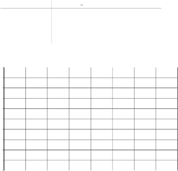
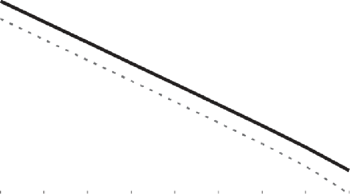
Figure 6.5
Tolerable
J
performance as a function of carrier tracking threshold, assuming all sig-
nals have the same tracking threshold.
nal levels are considered. This is because the GNSS signal power received at the
antenna input is so small. To demonstrate how little jammer power is required at the
input of a GNSS receiver to disable it when the receiver
J
/
S
performance in units of
decibels has been determined, the following equation is required:
() () ()
JS
=
J
−
S
(6.26)
r
r
dB
dB
dB
where:
(
J
r
)
dB
=
incident jammer power at the receiver antenna input (dBW)
(
S
r
)
dB
=
incident signal power at the receiver antenna input (dBW)
Rearranging (6.26), (
J
r
)
dB
=
(
J
/
S
)
dB
+
(
S
r
)
dB
. Since (
J
r
)
dB
=
10log
10
J
r
, then the jammer
power in watts at the antenna input is


Search WWH ::

Custom Search