Global Positioning System Reference
In-Depth Information
mit them to be synchronized to the code accumulator. The first thought might be to
design the code generator shift registers such that they contain the linear counters
that are synchronized by the hardware and read by the receiver baseband process.
However, the phase states of the code generators must be controlled by the receiver
baseband process. So a better design is to use code setters in the hardware and main-
tain the code accumulator in the receiver baseband processor. By far, the simplest
case is the C/A code generator setup, described first.
C/A Code Setup
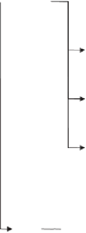
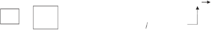
Figure 5.31 illustrates a high-level block diagram of the P and C/A code generators,
including their code setters. (Details of code generation were discussed in Chapter 4.)
Recall from Section 4.3.1.1 that the C/A code generator consists of two 10-bit linear
feedback shift registers called the G1 and G2 registers [2]. The C/A code setup
requires one 10-bit code setter to initialize both the G1 and G2 registers in the C/A
code generator. The phase states of the G1 and G2 registers are the same for every SV
forthesameGPStimeofweek.Itisthetapcombination on the G2 register (or equiva-
lently, the delay added to the G2 register) in combination with the G1 register that
determines the PRN number. A typical C/A code setter is capable of setting the G1
and G2 registers to their initial states and to their midpoint states. Since it requires
only 1 ms for the C/A code generator to cycle through its complete state, this code set-
ter design example holds the maximum delay to 1/2 ms until the C/A code generator
is synchronized to the code accumulator after initialization of the code setter. This
code setter design counts from 0 to 511 (1/2 C/A code epoch) and then rolls over.
Code
clock
2f
P code
clock
P code
advance /
retard (
X1A
code
setter
co
X1A
register
2)
÷
P code
X1B
code
setter
X1B
register
X1B
clock
control
37 to 1
MUX
X2A
code
setter
X2A
register
1
37
...
X2A
clock
control
X2 delay
register
X2B
code
setter
X2B
register
X2B
clock
control
G1
register
C/A code clock
C/A code
10 to 1 MUX
C/A code
advance /
retard (
C/A code
setter
÷
10
10
G2
register
2)
÷
10 to 1 MUX
Figure 5.31
GPS code setter and code generator block diagram.


Search WWH ::

Custom Search