Global Positioning System Reference
In-Depth Information
1
S
ω
0
(a)
+
1
S
1
S
ω
0
2
.
Σ
+
a
2
ω
(b)
+
+
1
S
1
S
1
S
ω
0
3
Σ
.
Σ
+
+
a
3
2
.
ω
b
3
ω
(c)
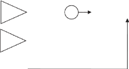
Figure 5.18
Block diagrams of: (a) first-, (b) second-, and (c) third-order analog loop filters.
Table 5.6
Loop Filter Characteristics
Loop
Order
Noise Bandwidth
B
n
(Hz)
Typical Filter
Values
Steady
State Error
Characteristics
ω
0
4
Sensitive to velocity stress.
Used in aided code loops and sometimes
used in aided carrier loops.
Unconditionally stable at all noise
bandwidths.
ω
0
B
n
=
First
(
dR
/
dt
)
0.25
ω
0
ω
0
ω
2
a
20
Sensitive to acceleration stress.
Used in aided and unaided carrier loops.
Unconditionally stable at all noise
bandwidths.
Second
2
2
2
ω
0
(
1
4
+
a
)
(
dR dt
/
)
2
ω
=
1 414
.
ω
a
0
ω
2
2
0
B
n
=
0.53
ω
0
ω
3
a
3
ω
03
2
(
ab
ab
+−
a
2
b
)
3
3
(
dR dt
/
)
Third
Sensitive to jerk stress.
Used in unaided carrier loops.
Remains stable at
B
n
≤
3
3
2
2
ωω
0
=
11
.
3
4
(
−
1
)
ω
0
0
33
b
30
ω
=
24
.
ω
18 Hz.
0
B
n
=
0.7845
ω
0
Source:
[7].
Note:
The loop filter natural radian frequency,
ω
0
, is computed from the value of the loop filter noise bandwidth,
B
n
, selected by the
designer.
R
is the LOS range to the satellite. The steady state error is inversely proportional to the
n
th power of the tracking loop
bandwidth and directly proportional to the
n
th derivative of range, where
n
is the loop filter order. Also see footnote 1.


Search WWH ::

Custom Search