Global Positioning System Reference
In-Depth Information
−
155.5
C/A
−
1
−
158.5
P
−
L
1
−
161.5
or
P
−
L
2
−
164.5
C/A
−
2
0° 5°
20°
40°
60°
80°
90°
100°
User elevation angle (deg)
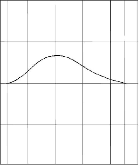
Figure 4.12
User received minimum signal power levels.
these two elevation angles, the minimum received signal power levels gradually
increase up to 2 dB maximum for the L1 signals and up to 1 dB maximum for the L2
signal and then decrease back to the specified minimums. This characteristic occurs
because the shaped beam pattern on the SV transmitting antenna arrays can only
match the required gain at the angles corresponding to the center of the Earth and near
the edge of the Earth, resulting in slightly increasing transmitting antenna array gain in
between these nadir angles. The user's antenna gain pattern is typically maximum at
the zenith and minimum at 5º above the horizon and for lower elevation angles.
The received signal levels are not expected to exceed
155.5
dBW, respectively, for the C/A code and P(Y) code components on the L1 and L2
channels [10]. Typically, the signal powers for the SVs are from 1 to 5 dB higher
than the minimum specified levels, depending on elevation angle and SV block, and
they remain nearly constant until their ends of life.
Table 4.6 tabulates the navigation satellite signal power budget for the Block II
GPS satellites adapted from [13] using the minimum user received power levels as
the starting point. It shows the output power levels at the worst-case off-axis angle
of 14.3º and for the assumed worst-case atmospheric loss of 0.5 dB. Referring to
Table 4.6, the link budget for the L1 C/A code to provide the signal power with a
unity gain transmitting antenna is:
−
153 dBW and
−
−
158.5
−
3.0
+
184.4
+
0.5
+
3.4
=
26.8 dBW.


Search WWH ::

Custom Search