Global Positioning System Reference
In-Depth Information
L2 signal
1,227.6 MHz
−
6dB
120 f
carrier
BPSK
modulator
0
×
120
P(Y) code data
or P(Y) code or
C/A code
⊕
data
⊕
BPSK
modulator
−
3dB
154
f
0
carrier
L1 signal
1,575.42 MHz
Σ
×
154
BPSK
modulator
90°
f
0
clock
P(Y) code
data
⊕
P(Y) code
generator
Limiter
P(Y) code
X1 epoch
X1 epoch
Switch
f
0
/10 clock
C/A code
generator
+
10
C/A code
⊕
data
1,000 Hz
Handover
information
+
20
X1 epoch
f
0
= 10.22999999543 MHz
50-bps data
50 Hz
Data
generator
Other
information
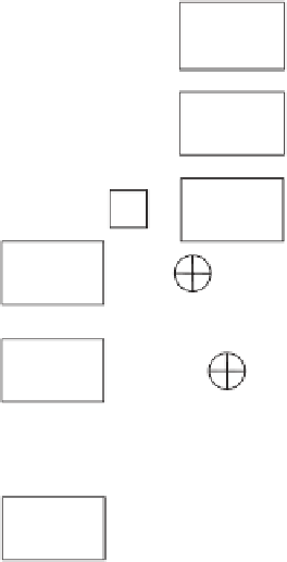
Figure 4.5
Legacy GPS satellite signal structure.
activated, the P code is encrypted to form what is known as the Y-code. The Y-code
has the same chipping rate as the P code. Thus, the acronym often used for the preci-
sion (encrypted) code is P(Y) code.
Since the PPS (primarily military) users have access to the cryptographic keys
and algorithms used in the AS process but the SPS (primarily civil) users do not, then
AS denies access to the P code by SPS users. In the past, both the C/A code and the
P(Y) code, as well as the L1 and L2 carrier frequencies, were subjected to an
encrypted time-varying frequency offset (referred to as
dither
) plus an encrypted
ephemeris and almanac offset error (referred to as
epsilon
) known as SA. SA denied
the full accuracy of GPS to the stand-alone SPS users. However, SA has been deacti-
vated on all GPS satellites since May 1, 2000, so this subject will not be further
discussed in this chapter.
Note in Figure 4.5 that the same 50-bps navigation message data is combined
with both the C/A code and the P(Y) code prior to modulation with the L1 carrier.
An exclusive-or logic gate is used for this modulation process, denoted by
⊕
. Since
data are both synchronous operations, the bit
transition rate cannot exceed the chipping rate of the PRN codes. Also note that
BPSK modulation is used with the carrier signals. The P(Y) code
the C/A code
⊕
data and P(Y) code
⊕
⊕
data is modulated
in phase quadrature with the C/A code
data on L1. As shown in Figure 4.5, the L1
carrier is phase shifted 90º before being BPSK modulated by the C/A code
⊕
data.
Then this result is combined with the attenuated output of the BPSK modulation of
L1 by the P(Y) code
⊕
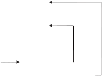
data. The 3-dB amplitude difference and phase relationship
between P code and C/A code on L1 are illustrated by the vector phase diagram in
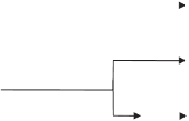
Figure 4.6. Figure 4.7 illustrates the result of P code
⊕
data. As
observed in Figure 4.7, the exclusive-or process is equivalent to binary multiplica-
⊕
data and C/A
⊕


Search WWH ::

Custom Search