Environmental Engineering Reference
In-Depth Information
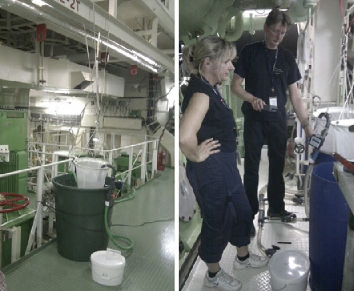
Fig. 14
Sampling arrangements for in-line sampling on vessels, on the
left
in a more open space,
and on the
right
in more confi ned space of the engine room
Sampling Point
Vessels are of very different sizes, design and arrangements, mainly depending on
their purpose and age. Consequently, also the ballast water systems are very differ-
ent in capacities and designs. Regarding appropriate sampling points the G2
Guidelines recommend the installation of an isokinetic sampling point/facility,
which diameter is related to the diameter of the ballast discharge line where it is
installed. Therefore it is expected that a range of different sampling points may be
found on different vessels. This poses a real challenge to PSC to have the adequate
sampling equipment for all different sampling points available. All hoses and con-
nections would then also need to be of the same size/diameter as the sampling point.
As per the authors sampling experience for type approval tests of BWMS most
vessels have installed 1 in. sampling points, which has shown to deliver enough
water fl ow for the sampling purpose.
Guidelines G2 defi nes the “sampling facilities” as the equipment installed to take
the sample and the “sampling point” as that place in the ballast water piping where
the sample is taken. This means that the sampling point is part of the vessel's main
pipe where the sampling facility is installed. Guideline G2 provides further details
for isokinetic sampling facilities:
Search WWH ::

Custom Search