Information Technology Reference
In-Depth Information
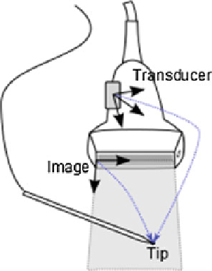
Fig. 5 Spatial calibration of
the transducer can be
performed by recording the
pointer tip position in the
Transducer coordinate system
and marking them in the
image
as intersection points or lines) from the image automatically, then compute the
transform that minimizes the difference between the expected and the measured
positions of the features.
Intersection of a thin linear object (such as a wire or needle) and the image plane
show up on the image clearly, as a bright spot. Automatic detection of small bright
spots in an image is a relatively simple task and the position of the spot usually can
be determined very accurately, therefore many calibration phantoms contain a
number of wires at known positions. A particularly interesting setup is when wires
are arranged in multiple N-shaped patterns (Fig.
6
), because if the wire positions are
known in 3D and the relative distances of the intersection points in the image are
known in 2D, the position of the middle wire intersection can be computed in 3D [
2
].
Arranging wires in planes have the additional advantage that the intersection points
in the image are collinear, which can be used for automatically rejecting bright spots
in the image that do not correspond to an actual wire intersection point (Fig.
7
).
Having 3 N-shaped wire pattern is shown to be enough to reach submillimeter
calibration accuracy [
2
]. Fully automatic, open-source implementation of the N-
wire-based probe calibration is available in the Plus toolkit [
3
]. The advantage of the
method is that is fully automatic, therefore a large number of calibration points can
be collected and so the effect of random errors can be reduced, the results not depend
much on the operator, and the calibration can be completed within a few minutes.
The disadvantage of the method is that it requires measurement of the wire positions
in the tracker coordinate system (typically by landmark registration of the calibration
phantom), requires phantom fabrication, and attention has to be paid to set imaging
parameters that allow accurate automatic detection of the wire intersections.
Other automatic methods have been proposed that use a simpler calibration
phantom. For example, it is possible to compute the probe calibration just by
imaging a
flat surface while completing certain motion patterns with the transducer.
This method is called single-wall calibration. The advantage of the method that it
fl