Information Technology Reference
In-Depth Information
(a) Differences between pre-operative 2D and pre-operative 3D
(b) Differences between pre-operative 2D and post-operative
(c) Differences between pre-operative 3D and post-operative
(d) Greater deviation between the two pre-operative to post-operative differences
—
from (b) and (c)
(e) Greatest deviations from (d) between resident and experienced staff surgeon
Several differences were observed in the 2D planning work
fl
ow and the 3D
planning work
ow. First, while best attempts were made to accurately extract the
dimensions of vertebrae with the 2D approach, deformation of the spinal column
and normal spine curvature contributed to signi
fl
cant errors in the initial estimate
with the 2D method. Figure
4
shows these differences in one of the 10 cases.
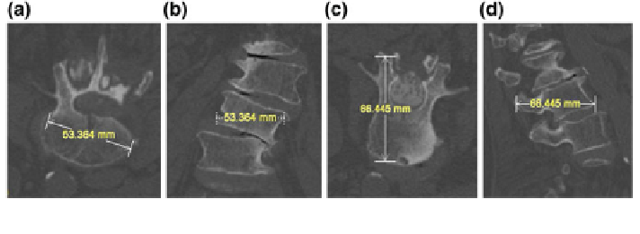
Because the axial slices do not necessary cut across the long axis of each vertebra, a
simple measurement in one slice is inadequate for accurate assessment. In Fig.
4
,
the width of the vertebra appears to be 53.364 mm in the axial view (a) of this CT
image, but the same linear segment in the sagittal view (b) clearly shows the
misleading nature of the measurement, due to the oblique orientation of the ver-
tebral body with respect to the entire patient. Figure
4
also shows the depth of a
vertebra along the pedicle to be 66.4 mm in the axial view (c) of this CT image. The
coronal view (d) of the same segment, however, shows a measurement that actually
represents a corner to corner distance, which likely may not be the measurement
intended. Both of these illustrations show the potential problems if screw length
decisions are based solely on standard 2D axial, sagittal or coronal views. The
potential for implant size and/or angulation error is increased further by the manual
nature of current 2D spine surgery planning methods.
Another difference is the consistency of the planning report. Although there is a
pre-de
ned manual entry form which is used routinely for spine planning, the use of
this form is inconsistent from case to case. Figure
5
shows the plan from one of the
cases. Because the process is manual, there are blank columns on the left and the
scratched out numbers at the bottom. It is unclear if the surgeon neglected to
ll in
those angles or if the angles were 0
and therefore not entered. The values that
were scratched out may possibly lead to transcription errors. In contrast,
°
the
Fig. 4 The corresponding width and depth segments shown from different orientations illustrate
the potential for misleading measurements when basing them on single 2D views