Information Technology Reference
In-Depth Information
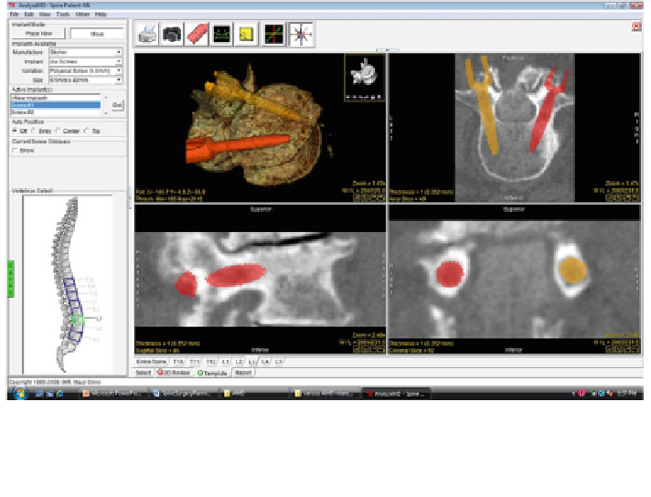
Fig. 3 Pedicle screw template placement. Screw templates are placed interactively into the image
data with the mouse. Each template corresponds to a particular prosthetic implant manufacturer.
The screws are evaluated in the orthogonal images and rendering to ensure that the screws are of
the appropriate length and thickness
required if the spinous process does not line up parallel to the y-axis in that view.
The realignment is also shown in Fig.
2
.
In the second step, digital templates of screws are selected and inserted into the
3D data. During the selection step, the appropriate type of pedicle screw is chosen
and a size is selected. The template is then placed into the axial image that includes
the widest portion of the pedicle. The virtual pedicle screw can now be translated or
rotated interactively in any of the three orthogonal views to achieve optimal
placement within the vertebra, as shown in Fig.
3
. Exact dimensions and angle
placement for each screw placed is automatically recorded for use in the
nal
report, which is the last step in the 3D spine surgery planning process. The report
provides a list of each screw templated, including the vertebra in which they are
placed, the manufacturer of the screw, the dimensions of the implant, and the
precise location within the vertebral body based on the axial and sagittal angles. In
addition to the implant list, a number of images are automatically generated and
added to the report for visual veri
cation.
3.2.3 Fastening Strength Formulation
According to strength of materials principles and theories of failure, each screw
withstands a maximum force before it can be torn away from the material after its
insertion. The holding power of a typical screw depends on the dimensions of the