Information Technology Reference
In-Depth Information
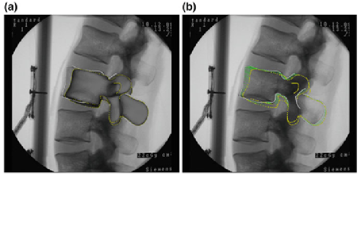
Fig. 5 Screenshots of establishing image-to-model correspondences. a the apparent contours
(yellow dots) of the mean model (dark grey) of the complete-PDM after the landmark-based
initialization. b 2D/2D correspondences (green lines) between the image contours (white) and the
projections of the apparent contours
mean model as shown in Fig.
5
a is presented in b. The obtained 2D point pairs are
then used to set up a set of 3D point pairs so that we turn a 2D/3D reconstruction
problem to a 3D/3D one. For details about how the proposed non-rigid 2D point
matching process works and about the mathematic proof of how the proposed
process eliminates the cross-matching event, we refer to our previous work [
28
]. In
the following, the details about how to convert the 2D/3D reconstruction problem to
a 3D/3D one and how the latter problem is solved are given for completeness.
3.3.1 Converting a 2D/3D Problem to a 3D/3D One
Assume that a set of 2D matched point pairs
have
been found, where A
b
is the projection of a point on the apparent contours of a 3D
model that is instantiated from the PDM and I
b
is a point on the image contours that
is matched to A
b
; n is the number of point pairs. The corresponding 3D point pairs
are then constructed as follows (see Fig.
6
for a schematic illustration). For a 2D
point I
b
, one can
f
ð
A
b
;
I
b
Þ;
b
¼
0
;
1
; ...;
n
1
g
find a projection ray r
b
emitting from the focal point of the X-ray
image through the point I
b
. Additionally, for its matched point A
b
, one knows the
associated 3D point
X
b
on the apparent contours of the model whose projection
onto the image is A
b
. By computing a point v
b
on the rayr
b
that has the shortest
distance to
X
b
, a 3D point pair
can be obtained. Combining all these 3D
point pairs, one can establish 2D/3D correspondence between the input image and a
3D model instantiated from the PDM, and thus convert a 2D/3D reconstruction
problem to a 3D/3D one.
ðX
b
;
v
b
Þ