Information Technology Reference
In-Depth Information
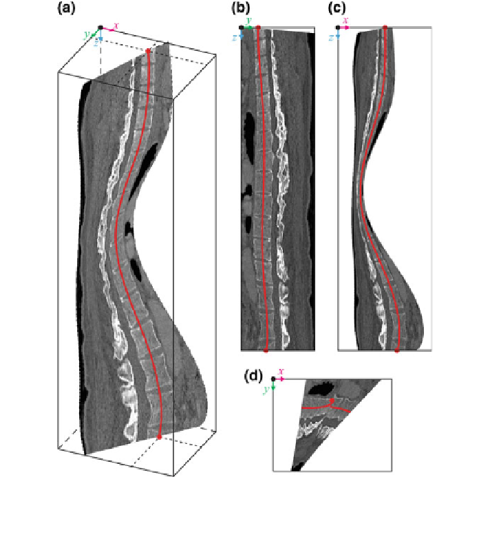
Fig. 24 A sagittal oblique curved-planar cross-section CT
u¼u
c
;/
¼
/
p
of a 3D CT image of a scoliotic
spine, shown in a 3D view, b left sagittal view, c posterior coronal view and d superior axial view
of the image-based coordinate system (Note The image-based coordinate system and the spine
curve correspond to Figs.
1
and
7
)
C
u¼u
c
;/
¼
/
p
ð
y
;
c
z
ð
i
ÞÞ
¼
I
ð
R
t
ð
i
Þ
ðuð
i
Þþ/
p
Þ
R
x
ðað
i
ÞÞ
½
c
x
ð
i
Þþ
D
x
;
y
;
c
z
ð
i
ÞÞ;
ð
85
Þ
where matrix R
t
ð
i
Þ
ðuð
i
Þþ/
p
Þ
(Eq.
19
) represents the axial vertebral rotation for
ned by t
angle
uð
i
Þþ/
p
about axis de
ð
i
Þ
(i.e.
uð
i
Þ
¼
u
w
ð
i
Þ
, Eq.
14
), and matrix
ð
t
y
ð
Þ=
t
z
ð
R
x
ðað
i
ÞÞ
(Eq.
52
) represents the rotation for angle
að
i
Þ
¼
arctan
i
i
ÞÞ
about
axis x of the image-based coordinate system, considering that t^ðiÞ
Þ
¼ t
x
ð
Þ;
t
y
ð
Þ;
t
z
ð
ð
i
i
i
i
Þ
is the unit tangent vector to the spine curve, and cðiÞ
ð
i
Þ
¼
ð
c
x
ð
i
Þ;
c
y
ð
i
Þ;
c
z
ð
i
ÞÞ
is the
center of rotation for every point i on the spine curve cðiÞ.
. Figure
24
displays
the sagittal oblique curved-planar cross-section that passes through the spine curve
(i.e.
D
x ¼ 0) and is rotated for
/
¼
/
p
¼ 25
.
ð
i
Þ