Information Technology Reference
In-Depth Information
with the center of rotation at point p
j
(Eq.
57
), arbitrarily chosen among points p
1
,
p
2
and p
3
. On the other hand, in the case of scoliotic spines, the rotation matrix is
rede
ned as R
s
and used to obtain the generalized oblique multi-planar cross-
section M
p
1
;
p
2
;
p
3
:
2
4
3
5
;
e
2x
n
Px
e
1x
M
p
1
;
p
2
;
p
3
ð
x
;
z
Þ
¼I
ð
R
s
R
s
½x
;
y
j
;
z
Þ;
¼
e
2y
n
Py
e
1y
ð
74
Þ
e
2z
n
Pz
e
1z
with the center of rotation again at point p
j
(Eq.
57
), arbitrarily chosen among points
p
1
, p
2
and p
3
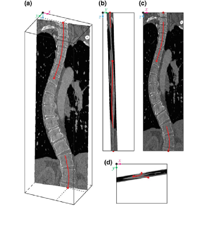
. Figure
20
displays the generalized oblique multi-planar cross-section
Fig. 20 A generalized oblique multi-planar cross-section M
p
1
;
p
2
;
p
3
of a 3D CT image of a scoliotic
spine, shown in a 3D view, b left sagittal view, c posterior coronal view and d superior axial view
of the image-based coordinate system (Note The image-based coordinate system and the spine
curve correspond to Figs.
1
and
7
)