Information Technology Reference
In-Depth Information
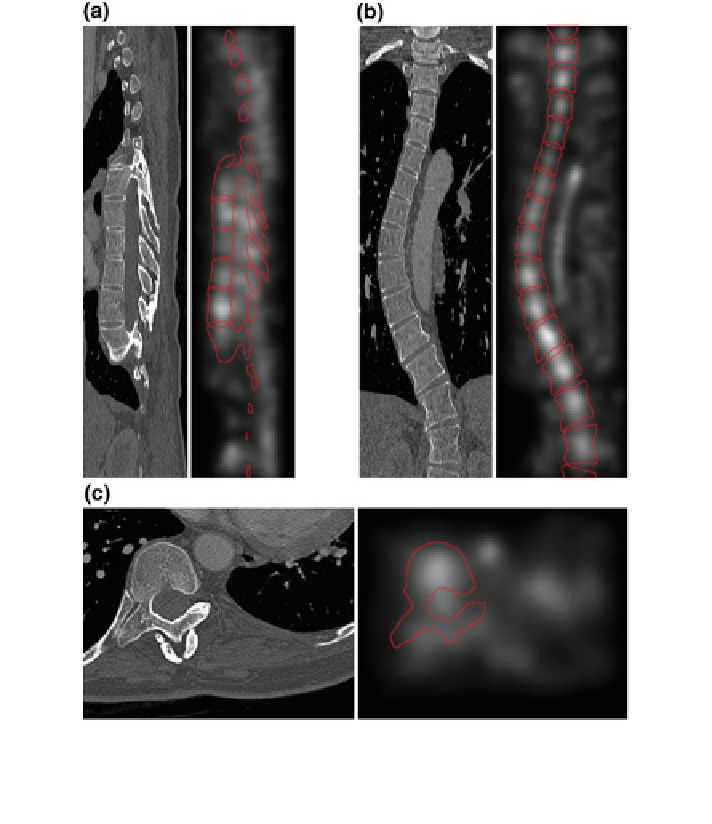
Fig. 13 Original image I (left) and the corresponding accumulator A
I
with superimposed spine
boundaries (right), displayed for a selected a sagittal, b coronal and c axial cross-section of a 3D
CT image of a scoliotic spine. In the accumulator A
I
, brighter elements correspond to a larger
number of intersections of lines connecting opposite edge points
intersection of the 3D image with the reconstruction plane, on which image
intensities are sampled. In CT imaging, reconstruction planes are usually trans-
versely oriented, while in MR imaging they are usually oriented parallel to the
excited slab. In both cases, the image reconstruction planes and the corresponding
original cross-sections de
ne the image-based coordinate system (Sect.
2.1.1
).
The established techniques for 2D visualization of anatomical structures are
therefore based on multi-planar reformation (MPR) that results in a series of
sagittal, coronal and axial multi-planar cross-sections. However, multi-planar cross-
sections do not always follow curved or tubular anatomical structures (e.g. spine,
arteries, colon). As all of the important parts of the structure are not simultaneously
visible in a single multi-planar cross-section, the visualization of such structures is