Information Technology Reference
In-Depth Information
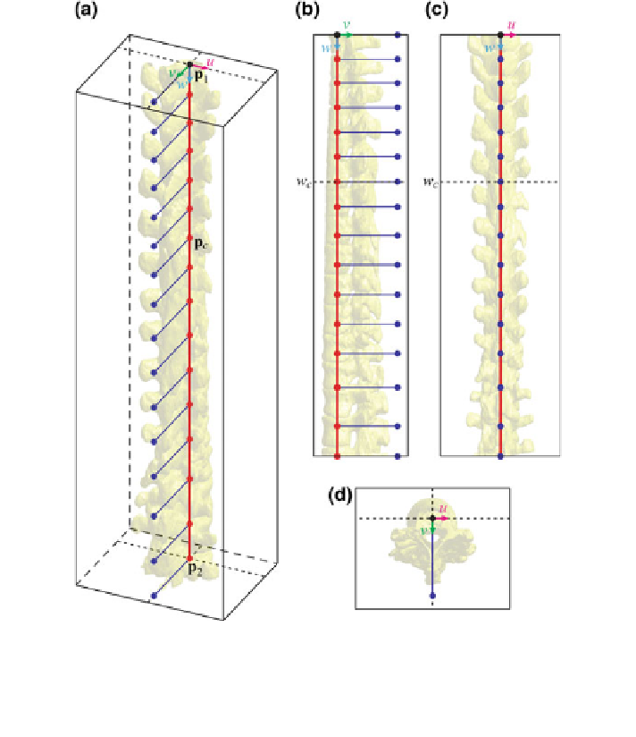
Fig. 8 The spine curve (red line) and axial vertebral rotation (blue directions) in the spine-based
coordinate system
3
S
of a 3D image of a scoliotic spine, shown in a 3D view, b left sagittal view,
c posterior coronal view and d superior axial view. The spine curve is defined between the start
point p
1
and end point p
2
, while the coordinates are shown also for a selected point p
c
¼
ð
R
u
c
;
v
c
;
w
c
Þ
on the spine curve
n
u
ð
the image-based coordinate system, then the modi
ed unit normal vector
i
Þ
equals:
Þ
¼t
e
Iy
t
^
ÞÞ
^
n
u
ð
i
ð
i
Þð
R
z
ðu
z
ð
i
ð
i
ÞÞ;
ð
16
Þ
where matrix R
z
ðu
z
ð
i
ÞÞ
represents the rotation for angle
u
z
ð
i
Þ
about axis z of the
image-based coordinate system: