Chemistry Reference
In-Depth Information
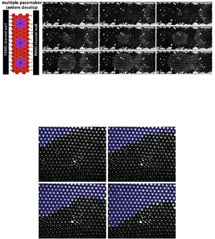
Fig. 5.10
Formation of target waves with multiple pacemaker centers in a oscillator network
confined in a PDMS microchannel.
Left
Schematic of the oscillators in a PDMS channel. PDMS, in
addition to the oil phase, absorbs the excitatory and inhibitory components of the BZ at the edges
(shown by the
arrows
).
Right
Two target wave patterns seen in the channel. One target wave is
forming at a pacemaker center clearly visible. The center of target pattern coming in from the right
is not visible
Fig. 5.11
Travelling waves are formed in large densely connected oscillator networks. Each image
is spaced 5 s apart. The excitation is
coloured blue
for easy visualization
expected that since the BZ concentrations are rather uniform over the network, a ran-
dom trigger in one of the oscillators can set off a cascading wave of activity, which
repeats periodically. However, we were not able in this scenario to find the precise
conditions and locations at which the waves were triggered.
Spiral waves formed in our experiments, when the hexagonal packing was not
perfect such that not every oscillator is coupled to six nearest neighbours. Yet, the
networks were not so sparse as to form 'islands' or 'peninsulas', where target waves
were predominant. An instance of a spiral is seen in Fig.
5.12
. A spiral wave can
be clearly seen among the oscillator population. A closer look into the network