Hardware Reference
In-Depth Information
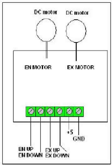
Figure 1.9
displays the schematic circuitry of two DC driver motors, which is respons-
ible to lift up or down any arm gate at either entrance or exit of the parking garage. When
EN UP = 1 and EN Down = 0, signals are set accordingly, the motor rotates in counter-
clockwise direction to lift the arm gate at the entrance of the garage. The gate returns to its
initial position when EN Down = 1 (EN UP = 0) which causes the motor to rotate in a
clockwise direction. The same is true for the EX DC motor.
Figure 1.10
illustrates the pictorial diagram of the circuit related to the two arm gates
used in this project. When limit switches 1 and 2 in
Figure 1.10
are activated, then the mi-
crocontroller is informed that the entrance arm gate is either closed (its normal position) or
open. Also when limit switches with names 3 and 4, it means that the exit arm gate is either
in its normal position (closed) or open position.
Figure 1.9
Search WWH ::

Custom Search