Information Technology Reference
In-Depth Information
#7
#1
#0
A
21
A
20
#7
#1
#0
#7
#1
#0
#7
#1
#0
D
7
D
1
D
0
A
19
-
A
0
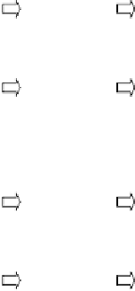
Figure 7.6 Organization of a 4M 8-bit memory using 1M 1-bit memory chips
(leakage of the stored charge on the capacitor), dynamic memory requires periodical
(every few milliseconds) refreshment in order to restore the stored logic values.
Figure 7.7 illustrates the dynamic memory array organization. The read
write cir-
cuitry in Figure 7.7 performs the functions of sensing the value on the bit line, ampli-
fying it, and refreshing the value stored on the capacitor.
In order to perform a read operation, the bit line is precharged high (same as in
static memory) and the word line is activated. That will cause the value stored on the
capacitor to appear on the bit line, thus appearing on the data line D
i
. As can be seen,
a read operation is destructive; that is, the capacitor is charged to the bit line. There-
fore, every read operation is followed by a write operation of the same value.
In order to perform a write operation, the intended value is placed on the bit line
and the word line is activated. If the intended value is 1, then the capacitor will be
charged, while if the intended value is 0, then the capacitor will be discharged.
Table 7.2 summarizes the operation of the control circuitry.
/
TABLE 7.2 Operation of the Control Circuitry
R
=
CE
W
Operation
0
None
1
1
Read
1
0
Write
¼
don't care


Search WWH ::

Custom Search