Information Technology Reference
In-Depth Information
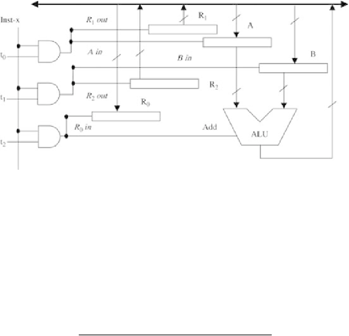
Figure 5.9 Signals generated to execute Inst-x on one-bus datapath during time period t
0
, t
1
, t
2
implementation using a simple example. Assume that the instruction set of a
machine has the three instructions: Inst-x, Inst-y, and Inst-z; and A, B, C, D, E, F,
G, and H are control lines. The following table shows the control lines that
should be activated for the three instructions at the three steps t
0
,
t
1
, and t
2
.
Step
Inst-x
Inst-y
Inst-z
t
0
D, B, E
F, H, G
E, H
t
1
C, A, H
G
D, A, C
t
2
G, C
B, C
The Boolean expressions for control lines A, B, and C can be obtained as follows:
A
¼
Inst-x
t
1
þ
Inst-z
t
1
¼
(Inst-x
þ
Inst-z)
t
1
B
¼
Inst-x
t
0
þ
Inst-y
t
2
C
¼
Inst-x
t
1
þ
Inst-x
t
2
þ
Inst-y
t
2
þ
Inst-z
t
1
¼
(Inst-x
þ
Inst-z)
t
1
þ
(Inst-x
þ
Inst-y)
t
2
Figure 5.10 shows the logic circuits for these control lines. Boolean expressions
for the rest of the control lines can be obtained in a similar way. Figure 5.11 shows
the state diagram in the execution cycle of these instructions.
5.5.2. Microprogrammed Control Unit
The idea of microprogrammed control units was introduced by M. V. Wilkes in the
early 1950s. Microprogramming was motivated by the desire to reduce the complex-
ities involved with hardwired control. As we studied earlier, an instruction is


Search WWH ::

Custom Search