Information Technology Reference
In-Depth Information
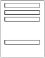
Memory System
Instructions
Data
CPU
ALU
Control Unit
Registers
Input / Output
Figure 5.1 Central processing unit main components and interactions with the memory
and I
/
O
simple execution cycle can be summarized as follows:
1. The next instruction to be executed, whose address is obtained from the PC, is
fetched from the memory and stored in the IR.
2. The instruction is decoded.
3. Operands are fetched from the memory and stored in CPU registers, if needed.
4. The instruction is executed.
5. Results are transferred from CPU registers to the memory, if needed.
The execution cycle is repeated as long as there are more instructions to execute.
A check for pending interrupts is usually included in the cycle. Examples of inter-
rupts include I
O device request, arithmetic overflow, or a page fault (see Chapter 7).
When an interrupt request is encountered, a transfer to an interrupt handling routine
takes place. Interrupt handling routines are programs that are invoked to collect the
state of the currently executing program, correct the cause of the interrupt, and
restore the state of the program.
The actions of the CPU during an execution cycle are defined by micro-orders
issued by the control unit. These micro-orders are individual control signals sent
over dedicated control lines. For example, let us assume that we want to execute an
instruction that moves the contents of register X to register Y. Let us also assume
that both registers are connected to the data bus, D. The control unit will issue a con-
trol signal to tell register X to place its contents on the data bus D. After some delay,
another control signal will be sent to tell register Y to read from data bus D. The acti-
vation of the control signals is determined using either hardwired control or micropro-
gramming. These concepts are explained later in this chapter.
/


Search WWH ::

Custom Search