Graphics Reference
In-Depth Information
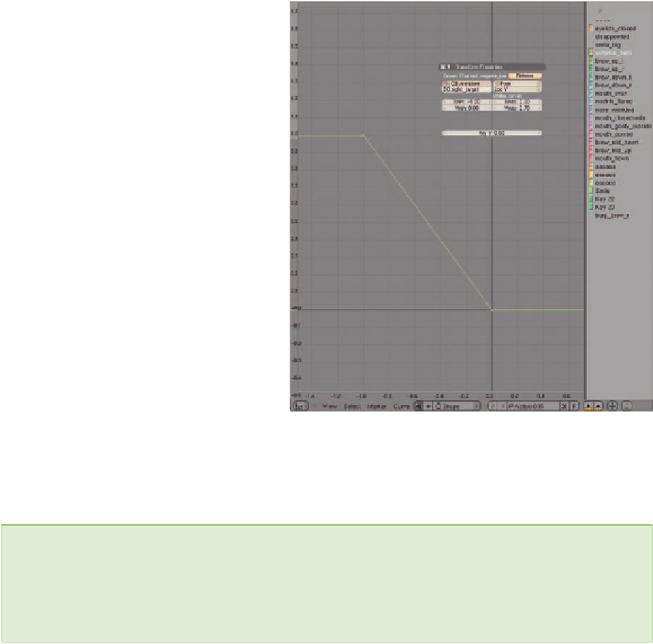
and the Y-axis, which is the shape strength,
goes from 0.0 to 1.0 over the same distance.
Figure 10.38 shows what this looks like. To
bind a second shape to a control, then, is as
simple as following the previous instructions
for the new shape but editing the created
curve afterward. Curves are edited just like
meshes in the 3D view—by using the
Tab
key
to enter Edit mode, right mouse but-
ton selecting individual vertices and moving
them around. And, just like the 3D view, you
can enter precise values for vertex locations
right in the properties panel.
To break it down, when you have used the
I-key
to create the default mapping line,
select it with the
RMB
. Use the
Tab
key to
enter Edit mode. Right mouse button select
the upper right hand vertex of the line,
which should be at (1,1) in the editor. On
the
Transform Properties
panel, change
the
Vertex X
fi eld from
1.0
to
1.0
.
Change the extrapolation type to
Constant
.
Done.
Figure 10.38
A curve for mapping a shape to reverse motion of a bone
NOTE
When working with rotations for your controls, you need to keep in mind a little idiosyncrasy
of Blender's curve editor. Rotations appear there divided by 10. Weird but true. So, if you want
your shape to engage over a 180 degree rotation, you cannot use 0.0 through 180.0 on the
X-axis. Instead, you must use
0.0
through
18.0
.
The control now functions as shown back in Figure 10.35. Moving it vertically between 0 and 1 units will
engage the “brow_up” shape, while moving it between 0 and
1 will engage “brow_down.”
As you may be guessing, setting up controls like this for any large number of shapes can be tedious, and you
would be correct. It is tedious. But it must be done to give a decent level of intuitive control over expressions
when you begin to animate.
Search WWH ::

Custom Search